Infiniti FX35, FX50 (S51). Manual — part 305
CCS-40
< SYSTEM DESCRIPTION >
[ICC (FULL SPEED RANGE)]
CONVENTIONAL (FIXED SPEED) CRUISE CONTROL MODE FUNCTION
ICC System Display (On The Information Display)
System Control Condition Display
Push and hold the MAIN switch for longer than approximately 1.5 seconds. This mode will be in a standby
state for setting.
1.
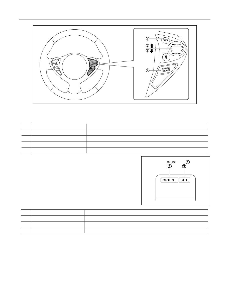
CANCEL switch
2.
RESUME/ACCELERATE switch
3.
SET/COAST switch
4.
MAIN switch
No.
Description
Function
1
CANCEL switch
Deactivates system without erasing set speed.
2
RESUME/ACCELERATE switch
Resumes set speed or increases speed incrementally.
3
SET/COAST switch
Sets desired cruise speed or reduces speed incrementally.
4
MAIN switch
Master switch to activate the system (Press for more than 1.5 seconds).
JSOIA0151ZZ
JSOIA0012ZZ
No.
Description
Function
1
ICC system warning lamp
Indicates that a malfunction occurs in the ICC system.
2
MAIN switch indicator
Indicates that the MAIN switch is ON (ICC system ON).
3
SET switch indicator
Indicates that the set conventional (fixed speed) cruise control mode is controlled.
CCS
CONVENTIONAL (FIXED SPEED) CRUISE CONTROL MODE FUNCTION
CCS-41
< SYSTEM DESCRIPTION >
[ICC (FULL SPEED RANGE)]
C
D
E
F
G
H
I
J
K
L
M
B
N
P
A
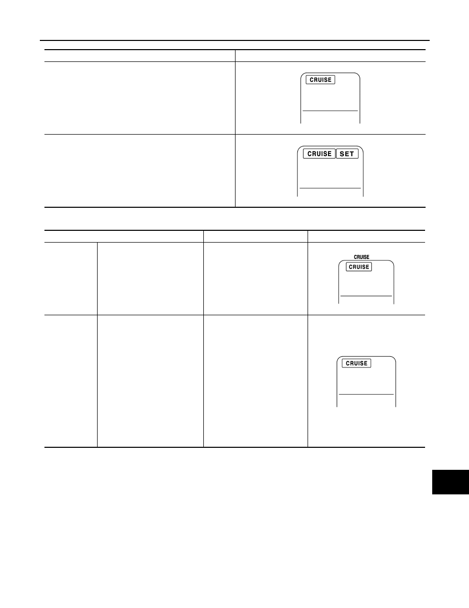
Warning and Automatic Cancellation Display
NOTE:
When the ICC system is automatically canceled, the cancellation condition can be displayed on “WORK SUPPORT” of CONSULT-III
(ICC).
Condition
Display on ICC system display
Standby mode
Control mode
JPOIA0158ZZ
JPOIA0156ZZ
Condition
Description
Display on ICC system display
Warning display
When the ICC system is malfunc-
tioning
A chime sounds and the control is
automatically canceled.
NOTE:
Turn the engine OFF and restart
engine. If there is no malfunction,
it is possible to set the system.
System cancel
display
• When brake pedal is depressed
• When pressing CANCEL switch
• When the vehicle speed falls be-
low approximately 32 km/h (20
MPH)
• When the vehicle slows down
more than 13 km/h (8 MPH) be-
low the set speed
• When the selector lever is not in
the “D”, “DS” position or manual
mode
• When the parking brakes are ap-
plied
• When VDC (including the TCS)
operates
• When a wheel slips
A chime sounds and the control is
automatically canceled.
NOTE:
• The system will be in a standby,
after the control is automatically
canceled.
• A chime sounds when the con-
trol is automatically canceled,
except when brake pedal is de-
pressed or when CANCEL
switch is pressed.
JPOIA0157ZZ
JPOIA0158ZZ
CCS-42
< SYSTEM DESCRIPTION >
[ICC (FULL SPEED RANGE)]
CONVENTIONAL (FIXED SPEED) CRUISE CONTROL MODE FUNCTION
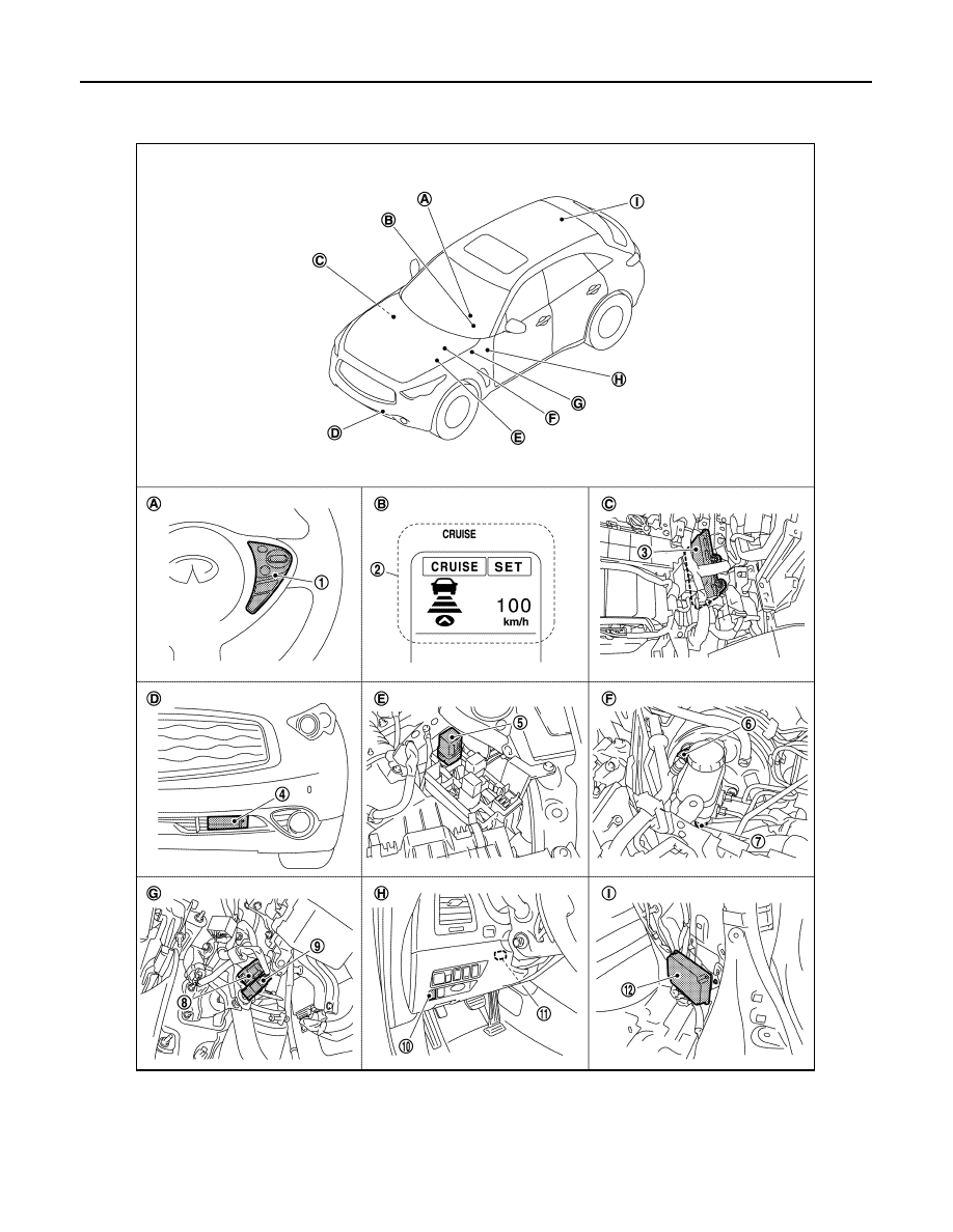
Component Parts Location
INFOID:0000000005501569
1.
ICC steering switch
2.
Information display, ICC system
warning lamp
3.
ECM
4.
ICC sensor integrated unit
5.
ICC brake hold relay
6.
Booster solenoid/Release switch
7.
Brake pressure sensor
8.
Stop lamp switch
9.
ICC brake switch
10. IBA OFF switch
11.
ICC warning chime
12. Brake booster control unit
JPOIA0194ZZ

CCS
CONVENTIONAL (FIXED SPEED) CRUISE CONTROL MODE FUNCTION
CCS-43
< SYSTEM DESCRIPTION >
[ICC (FULL SPEED RANGE)]
C
D
E
F
G
H
I
J
K
L
M
B
N
P
A
Component Description
INFOID:0000000005501570
×
: Applicable
*1: Vehicle-to-vehicle distance control mode
*2: Conventional (fixed speed) cruise control mode
*3: IBA system and Brake Assist (With Preview Function)
NOTE:
Only IBA system uses
A.
Steering wheel (RH)
B.
On the combination meter
C.
Behind the glove box
D.
Front bumper (LH)
E.
Engine room (LH)
F.
Inside brake master cylinder cover
G.
Upper side of brake pedal
H.
Instrument driver lower panel (LH)
I.
Luggage room (RH)
Component
Function Description
Description
*1
*2
*3
ICC sensor integrated unit
×
×
×
.
ECM
×
×
×
.
ABS actuator and electric unit (control
unit)
×
×
×
.
BCM
×
Transmits the front wiper request signal to ICC sensor inte-
grated unit via CAN communication.
TCM
×
×
.
Unified meter and A/C amp.
×
×
×
Receives the meter display signal, ICC warning lamp signal,
and IBA OFF indicator lamp signal from ICC sensor integrat-
ed unit via CAN communication and transmits them to the
combination meter via the communication line.
Combination meter
×
×
×
Performs the following operations using the signals received
from the unified meter and A/C amp. via the communication
line.
• Displays the ICC system operation status using the meter
display signal.
• Illuminates the ICC system warning lamp using the ICC
warning lamp signal.
• Illuminates the IBA OFF indicator lamp using the IBA OFF
indicator lamp signal.
ICC brake switch
×
×
×
.
Stop lamp switch
×
×
×
ICC brake hold relay
×
×
.
Brake booster control unit
×
×
×
.
Brake booster
×
×
.
Brake pressure sensor
×
×
.
Booster solenoid/Release switch
×
×
for booster solenoid.
for release switch.
ICC warning chime
×
×
×
.
Steering angle sensor
×
.
IBA OFF switch
×
NOTE
.
Нет комментариевНе стесняйтесь поделиться с нами вашим ценным мнением.
Текст