Infiniti FX35, FX50 (S51). Manual — part 1048
EXL-188
< ECU DIAGNOSIS INFORMATION >
[XENON TYPE]
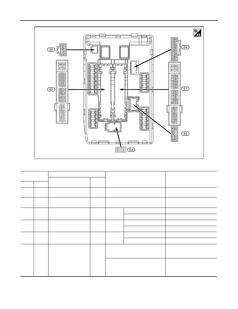
IPDM E/R (INTELLIGENT POWER DISTRIBUTION MODULE ENGINE ROOM)
TERMINAL LAYOUT
PHYSICAL VALUES
JSMIA0001ZZ
Terminal No.
(Wire color)
Description
Condition
Value
(Approx.)
Signal name
Input/
Output
+
−
1
(W)
Ground
Battery power supply
Input
Ignition switch OFF
Battery voltage
2
(L)
Ground
Battery power supply
Input
Ignition switch OFF
Battery voltage
4
(V)
Ground
Front wiper LO
Output
Ignition
switch ON
Front wiper switch OFF
0 V
Front wiper switch LO
Battery voltage
5
(L)
Ground
Front wiper HI
Output
Ignition
switch ON
Front wiper switch OFF
0 V
Front wiper switch HI
Battery voltage
7
(R)
Ground
Tail, license plate lamps &
interior lamps
Output
Ignition
switch ON
Lighting switch OFF
0 V
Lighting switch 1ST
Battery voltage
10
*1
(SB)
Ground
ECM relay power supply
Output
Ignition switch OFF
(More than a few seconds after turning
ignition switch OFF)
0 V
• Ignition switch ON
• Ignition switch OFF
(For a few seconds after turning igni-
tion switch OFF)
Battery voltage

IPDM E/R (INTELLIGENT POWER DISTRIBUTION MODULE ENGINE ROOM)
EXL-189
< ECU DIAGNOSIS INFORMATION >
[XENON TYPE]
C
D
E
F
G
H
I
J
K
M
A
B
EXL
N
O
P
11
(BR)
Ground
Steering lock unit power
supply
Output
Ignition
switch
OFF
A few seconds after open-
ing the driver door
Battery voltage
Ignition
switch
LOCK
Press the push-button ig-
nition switch
Battery voltage
Ignition switch ACC or ON
0 V
12
(B)
Ground
Ground
—
Ignition switch ON
0 V
13
(Y)
Ground
Fuel pump power supply
Output
Approximately 1 second or more after
turning the ignition switch ON
0 V
• Approximately 1 second after turning
the ignition switch ON
• Engine running
Battery voltage
16
(LG)
Ground
Front wiper stop position
Input
Ignition
switch ON
Front wiper stop position
0 V
Any position other than
front wiper stop position
Battery voltage
19
(W)
Ground
Ignition relay power supply
Output
Ignition switch OFF
0 V
Ignition switch ON
Battery voltage
25
(G)
Ground
Ignition relay power supply
Output
Ignition switch OFF
0 V
Ignition switch ON
Battery voltage
26
*2
(R)
Ground
Ignition relay power supply
Output
Ignition switch OFF
0 V
Ignition switch ON
Battery voltage
27
(Y)
Ground
Ignition relay monitor
Input
Ignition switch OFF or ACC
Battery voltage
Ignition switch ON
0 V
28
(O)
Ground
Push-button ignition
switch
Input
Press the push-button ignition switch
0 V
Release the push-button ignition switch
Battery voltage
30
(GR)
Ground
Starter relay control
Input
Ignition
switch ON
Selector lever in any posi-
tion other than P or N
0 V
Selector lever P or N
Battery voltage
32
(SB)
Ground
Steering lock unit condi-
tion-1
Input
Steering lock is activated
0 V
Steering lock is deactivated
Battery voltage
33
(P)
Ground
Steering lock unit condi-
tion-2
Input
Steering lock is activated
Battery voltage
Steering lock is deactivated
0 V
36
(G)
Ground
Battery power supply
Input
Ignition switch OFF
Battery voltage
39
(P)
—
CAN-L
Input/
Output
—
—
40
(L)
—
CAN-H
Input/
Output
—
—
41
(B)
Ground
Ground
—
Ignition switch ON
0 V
42
(Y)
Ground
Cooling fan relay control
Input
Ignition switch OFF or ACC
0 V
Ignition switch ON
0.7 V
Terminal No.
(Wire color)
Description
Condition
Value
(Approx.)
Signal name
Input/
Output
+
−

EXL-190
< ECU DIAGNOSIS INFORMATION >
[XENON TYPE]
IPDM E/R (INTELLIGENT POWER DISTRIBUTION MODULE ENGINE ROOM)
43
(SB)
Ground
A/T shift selector
(Detention switch)
Input
Ignition
switch ON
• Press the selector but-
ton (Selector lever P)
• Selector lever in any po-
sition other than P
Battery voltage
Release the selector but-
ton (selector lever P)
0 V
44
(W)
Ground
Horn relay control
Input
The horn is deactivated
Battery voltage
The horn is activated
0 V
45
(G)
Ground
Anti theft horn relay control
Input
The horn is deactivated
Battery voltage
The horn is activated
0 V
46
(BR)
Ground
Starter relay control
Input
Ignition
switch ON
Selector lever in any posi-
tion other than P or N
0 V
Selector lever P or N
Battery voltage
48
(L)
Ground
A/C relay power supply
Output
Engine
running
A/C switch OFF
0 V
A/C switch ON
(A/C compressor is oper-
ating)
Battery voltage
49
(W)
*1
(SB)
*3
Ground
ECM relay power supply
Output
Ignition switch OFF
(More than a few seconds after turning
ignition switch OFF)
0 V
• Ignition switch ON
• Ignition switch OFF
(For a few seconds after turning igni-
tion switch OFF)
Battery voltage
51
(G)
Ground
Ignition relay power supply
Output
Ignition switch OFF
0 V
Ignition switch ON
Battery voltage
52
(W)
Ground
Ignition relay power supply
Output
Ignition switch OFF
0 V
Ignition switch ON
Battery voltage
53
(W)
Ground
ECM relay power supply
Output
Ignition switch OFF
(More than a few seconds after turning
ignition switch OFF)
0 V
• Ignition switch ON
• Ignition switch OFF
(For a few seconds after turning igni-
tion switch OFF)
Battery voltage
54
(R)
Ground
Throttle control motor re-
lay power supply
Output
Ignition switch OFF
(More than a few seconds after turning
ignition switch OFF)
0 V
• Ignition switch ON
• Ignition switch OFF
(For a few seconds after turning igni-
tion switch OFF)
Battery voltage
55
(BR)
Ground
ECM power supply
Output
Ignition switch OFF
Battery voltage
56
(O)
*1
(V)
*3
Ground
Ignition relay power supply
Output
Ignition switch OFF
0 V
Ignition switch ON
Battery voltage
57
(LG)
Ground
Ignition relay power supply
Output
Ignition switch OFF
0 V
Ignition switch ON
Battery voltage
Terminal No.
(Wire color)
Description
Condition
Value
(Approx.)
Signal name
Input/
Output
+
−
IPDM E/R (INTELLIGENT POWER DISTRIBUTION MODULE ENGINE ROOM)
EXL-191
< ECU DIAGNOSIS INFORMATION >
[XENON TYPE]
C
D
E
F
G
H
I
J
K
M
A
B
EXL
N
O
P
58
(Y)
Ground
Ignition relay power supply
Output
Ignition switch OFF
0 V
Ignition switch ON
Battery voltage
69
(W)
Ground
ECM relay control
Output
Ignition switch OFF
(More than a few seconds after turning
ignition switch OFF)
Battery voltage
• Ignition switch ON
• Ignition switch OFF
(For a few seconds after turning igni-
tion switch OFF)
0 – 1.5 V
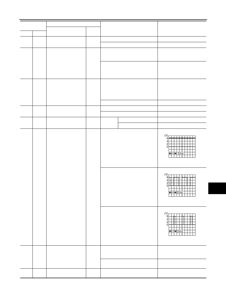
70
(O)
Ground
Throttle control motor re-
lay control
Output
Ignition switch ON
→
OFF
0 – 1.0 V
↓
Battery voltage
↓
0 V
Ignition switch ON
0 – 1.0 V
74
(G)
Ground
Ignition relay power supply
Output
Ignition switch OFF
0 V
Ignition switch ON
Battery voltage
75
(Y)
Ground
Oil pressure switch
Input
Ignition
switch ON
Engine stopped
0 V
Engine running
Battery voltage
76
(P)
*1
(V)
*3
Ground
Power generation com-
mand signal
Output
Ignition switch ON
6.3 V
40% is set on “ACTIVE TEST”, “AL-
TERNATOR DUTY” of “ENGINE”
3.8 V
80% is set on “ACTIVE TEST”, “AL-
TERNATOR DUTY” of “ENGINE”
1.4 V
77
(B)
*1
(L)
*3
Ground
Fuel pump relay control
Output
• Approximately 1 second after turning
the ignition switch ON
• Engine running
0 – 1.0 V
Approximately 1 second or more after
turning the ignition switch ON
Battery voltage
80
(W)
Ground
Starter motor
Output
At engine cranking
Battery voltage
Terminal No.
(Wire color)
Description
Condition
Value
(Approx.)
Signal name
Input/
Output
+
−
JPMIA0001GB
JPMIA0002GB
JPMIA0003GB
Нет комментариевНе стесняйтесь поделиться с нами вашим ценным мнением.
Текст