Infiniti FX35, FX50 (S51). Manual — part 38
ADP-144
< ECU DIAGNOSIS INFORMATION >
DRIVER SEAT CONTROL UNIT
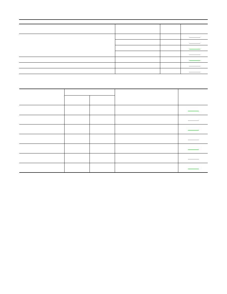
DTC Index
INFOID:0000000005249779
*1
:
• 0: Current malfunction is present
• 1-39: Displayed if any previous malfunction is present when current condition is normal. The numeral value increases by one at each
IGN ON to OFF cycle from 1 to 39. The counter remains at 39 even if the number of cycles exceeds it. However, the counter is reset
to 1 if any malfunction is detected again, the normal operation is resumed and the ignition switch is turned from OFF to ON.
Operating in
fail-safe mode
Malfunction Item
Related
DTC
Diagnosis
Only manual functions operate normally.
CAN communication
U1000
Tilt sensor
B2118
Telescopic sensor
B2119
Detent switch
B2126
Only manual functions, except door mirror, operate normally.
UART communication
B2128
Only manual functions, except seat sliding, operate normally.
Seat sliding output
B2112
Only manual functions, except seat reclining, operate normally.
Seat reclining output
B2113
CONSULT-III
display
Timing
*1
Item
Reference page
Current mal-
function
Previous mal-
function
CAN COMM CIRCUIT
[U1000]
0
1-39
CAN communication
SEAT SLIDE
[B2112]
0
1-39
Seat slide motor output
SEAT RECLINING
[B2113]
0
1-39
Seat reclining motor output
TILT SENSOR
[B2118]
0
1-39
Tilt sensor input
TELESCO SENSOR
[B2119]
0
1-39
Telescopic sensor input
DETENT SW
[B2126]
0
1-39
Detention switch condition
UART COMM
[B2128]
0
1-39
UART communication
AUTOMATIC DRIVE POSITIONER CONTROL UNIT
ADP-145
< ECU DIAGNOSIS INFORMATION >
C
D
E
F
G
H
I
K
L
M
A
B
ADP
N
O
P
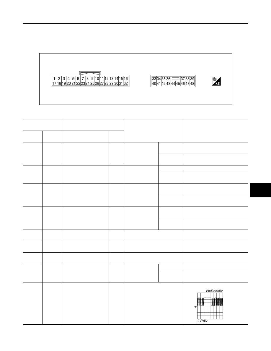
AUTOMATIC DRIVE POSITIONER CONTROL UNIT
Reference Value
INFOID:0000000005249780
TERMINAL LAYOUT
PHYSICAL VALUES
JMJIA0199ZZ
Terminal No.
(Wire color)
Description
Condition
Voltage (V)
(Approx.)
(+)
(-)
Signal name
Input/
Output
1
(Y)
Ground
Tilt switch up signal
Input
Tilt switch
Operate
(up)
0
Other than
above
5
2
(LG)
Ground
Changeover switch RH
signal
Input
Changeover
switch position
RH
0
Neutral or
LH
5
3
(G)
Ground
Mirror switch up signal
Input
Mirror switch
Operated
(up)
0
Other than
above
5
4
(V)
Ground
Mirror switch left signal
Input
Mirror switch
Operated
(left)
0
Other than
above
5
5
(R)
Ground
Door mirror sensor (RH)
up/down signal
Input
Door mirror RH position
Change between 3.4 (close to peak)
0.6 (close to valley)
6
(GR)
Ground
Door mirror sensor (LH)
up/down signal
Input
Door mirror LH position
Change between 3.4 (close to peak)
0.6 (close to valley)
7
(LG)
Ground
Tilt sensor signal
Input
Tilt position
Change between 1.2 (close to top) 3.4
(close to bottom)
9
(L)
Ground
Memory switch 1 signal
Input
Memory switch 1
Push
0
Other than
above
5
10
(V)
Ground
UART communication
(TX)
Output
Ignition switch ON
JMJIA0118ZZ

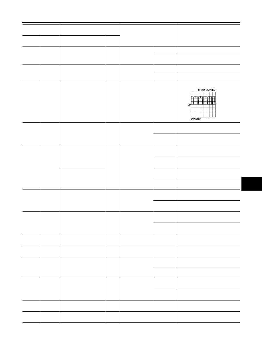
ADP-146
< ECU DIAGNOSIS INFORMATION >
AUTOMATIC DRIVE POSITIONER CONTROL UNIT
11
(SB)
Ground
Telescopic switch forward
signal
Input
Telescopic switch
Operate
(forward)
0
Other than
above
5
12
(O)
Ground
Memory indictor 1 signal
Output
Memory indictor 1
Illuminate
0
Other than
above
Battery voltage
13
(P)
Ground
Memory indictor 2 signal
Output
Memory indictor 2
Illuminate
0
Other than
above
Battery voltage
14
(O)
Ground
Door mirror motor (RH) up
output signal
Output
Door mirror RH
Operate
(up)
Battery voltage
Other than
above
0
15
(GR)
Ground
Door mirror motor (RH)
left output signal
Output
Door mirror RH
Operate
(left)
Battery voltage
Other than
above
0
16
(Y)
Ground
Door mirror motor (LH)
down output signal
Output
Door mirror (LH)
Operate
(down)
Battery voltage
Other than
above
0
Door mirror motor (LH)
right output signal
Operate
(right)
Battery voltage
Other than
above
0
17
(W)
Ground
Tilt switch down signal
Input
Tilt switch
Operate
(down)
0
Other than
above
5
18
(P)
Ground
Changeover switch LH
signal
Input
Changeover
switch position
LH
0
Neutral or
RH
5
19
(SB)
Ground
Mirror switch down signal
Input
Mirror switch
Operate
(down)
0
Other than
above
5
20
(BR)
Ground
Mirror switch right signal
Input
Mirror switch
Operate
(right)
0
Other than
above
5
21
(L)
Ground
Door mirror sensor (RH)
left/right signal
Input
Door mirror RH position
Change between 3.4 (close to left
edge) 0.6 (close to right edge)
22
(G)
Ground
Door mirror sensor (LH)
left/right signal
Input
Door mirror LH position
Change between 0.6 (close to left
edge) 3.4 (close to right edge)
23
(P)
Ground
Telescopic sensor signal
Input
Telescopic position
Change between 0.8 (close to top) 3.4
(close to bottom)
Terminal No.
(Wire color)
Description
Condition
Voltage (V)
(Approx.)
(+)
(-)
Signal name
Input/
Output
AUTOMATIC DRIVE POSITIONER CONTROL UNIT
ADP-147
< ECU DIAGNOSIS INFORMATION >
C
D
E
F
G
H
I
K
L
M
A
B
ADP
N
O
P
24
(R)
Ground
Set switch signal
Input
Set switch
Push
0
Other than
above
5
25
(SB)
Ground
Memory switch 2 signal
Input
Memory switch 2
Push
0
Other than
above
5
26
(Y)
Ground
UART communication
(RX)
Input
Ignition switch ON
27
(G)
Ground
Telescopic switch back-
ward signal
Input
Telescopic switch
Operate
(backward)
0
Other than
above
5
30
(R)
Ground
Door mirror motor (RH)
down output signal
Output
Door mirror (RH)
Operate
(down)
Battery voltage
Other than
above
0
Door mirror motor (RH)
right output signal
Operate
(right)
Battery voltage
Other than
above
0
31
(LG)
Ground
Door mirror motor (LH)
up output signal
Output
Door mirror (LH)
Operate
(up)
Battery voltage
Other than
above
0
32
(L)
Ground
Door mirror motor (LH)
left output signal
Output
Door mirror (LH)
Operate
(left)
Battery voltage
Other than
above
0
33
(W)
Ground
Sensor power supply
Input
—
5
34
(R)
Ground
Power source (Fuse)
Input
—
Battery voltage
35
(L)
Ground
Tilt motor up output signal
Output
Steering tilt
Operate
(up)
Battery voltage
Other than
above
0
36
(GR)
Ground
Telescopic motor forward
output signal
Output
Steering telescop-
ic
Operate
(forward)
Battery voltage
Other than
above
0
39
(W)
Ground
Power source (C/B)
—
Battery voltage
40
(B)
Ground
Ground
—
—
0
Terminal No.
(Wire color)
Description
Condition
Voltage (V)
(Approx.)
(+)
(-)
Signal name
Input/
Output
JMJIA0121ZZ
Нет комментариевНе стесняйтесь поделиться с нами вашим ценным мнением.
Текст