Infiniti FX35, FX50 (S51). Manual — part 775
AUTOMATIC SPEED CONTROL DEVICE (ASCD)
EC-641
< SYSTEM DESCRIPTION >
[VK50VE]
C
D
E
F
G
H
I
J
K
L
M
A
EC
N
P
O
Component Description
INFOID:0000000005237187
Component
Reference
ASCD steering switch
ASCD brake switch
Stop lamp switch
Electric throttle control actuator
ASCD indicator
EC-642
< SYSTEM DESCRIPTION >
[VK50VE]
CAN COMMUNICATION
CAN COMMUNICATION
System Description
INFOID:0000000005237188
CAN (Controller Area Network) is a serial communication line for real time application. It is an on-vehicle mul-
tiplex communication line with high data communication speed and excellent error detection ability. Many elec-
tronic control units are equipped onto a vehicle, and each control unit shares information and links with other
control units during operation (not independent). In CAN communication, control units are connected with 2
communication lines (CAN H line, CAN L line) allowing a high rate of information transmission with less wiring.
Each control unit transmits/receives data but selectively reads required data only.
Refer to
LAN-30, "CAN Communication Signal Chart"
, about CAN communication for detail.
COOLING FAN CONTROL
EC-643
< SYSTEM DESCRIPTION >
[VK50VE]
C
D
E
F
G
H
I
J
K
L
M
A
EC
N
P
O
COOLING FAN CONTROL
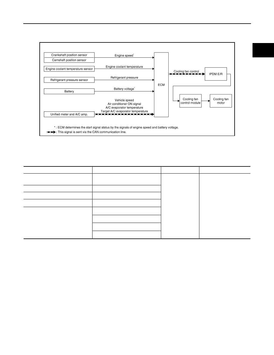
System Diagram
INFOID:0000000005237189
System Description
INFOID:0000000005237190
INPUT/OUTPUT SIGNAL CHART
*1: The ECM determines the start signal status by the signals of engine speed and battery voltage.
*2: This signal is sent to ECM via the CAN communication line.
SYSTEM DESCRIPTION
ECM controls cooling fan speed corresponding to vehicle speed, engine coolant temperature, air conditioner
ON signal, refrigerant pressure, target A/C evaporator temperature and A/C evaporator temperature.
Cooling fan control signal is sent to IPDM E/R from ECM via the CAN communication line. Then, IPDM E/R
sends ON/OFF pulse duty signal to cooling fan control module. Corresponding to this ON/OFF pulse duty sig-
nal, cooling fan control module gives cooling fan motor operating voltage to cooling fan motors. Cooling fan
speed is controlled by duty cycle of cooling fan motor operating voltage sent from cooling fan control module.
JMBIA1529GB
Sensor
Input signal to ECM
ECM function
Actuator
Crankshaft position sensor
Camshaft position sensor
Engine speed*
1
Cooling fan control
IPDM E/R
↓
Cooling fan control module
↓
Cooling fan motor
Engine coolant temperature sensor
Engine coolant temperature
Refrigerant pressure sensor
Refrigerant pressure
Battery
Battery voltage*
1
Unified meter and A/C amp.
Vehicle speed*
2
Air conditioner ON signal*
2
A/C evaporator temperature*
2
Target A/C evaporator temperature*
2
EC-644
< SYSTEM DESCRIPTION >
[VK50VE]
COOLING FAN CONTROL
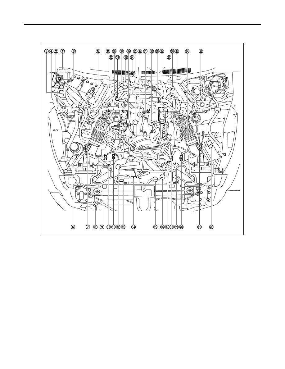
Component Parts Location
INFOID:0000000005589023
1.
IPDM E/R
2.
VVEL control module
3.
Battery current sensor
4.
VVEL actuator motor relay
5.
Cooling fan relay-1
6.
Cooling fan relay-2
7.
Mass air flow sensor (bank 2)
8.
Refrigerant pressure sensor
9.
Exhaust valve timing control position
sensor (bank 2)
10. Exhaust valve timing control sole-
noid valve (bank 2)
11.
Camshaft position sensor (bank 2)
12. Intake valve timing control solenoid
valve (bank 2)
13. Cooling fan motor-1
14. Cooling fan control module-1
15. Cooling fan motor-2
16. Cooling fan control module-2
17. Intake valve timing control solenoid
valve (bank 1)
18. Camshaft position sensor (bank 1)
19. Exhaust valve timing control sole-
noid valve (bank 1)
20. Exhaust valve timing control position
sensor (bank 1)
21. Mass air flow sensor (with intake air
temperature sensor) (bank 1)
22. ICC brake hold relay (ICC models)
23. Brake booster pressure sensor
24. Ignition coil (with power transistor)
and spark plug (bank 1)
25. VVEL actuator motor (bank 1)
26. VVEL control shaft position sensor
(bank 1)
27. Fuel injector (bank 1)
28. Electric throttle control actuator
(bank 1)
29. A/F sensor 1 (bank 1)
30. Knock sensor (bank 1)
JMBIA1535ZZ
Нет комментариевНе стесняйтесь поделиться с нами вашим ценным мнением.
Текст