Infiniti FX35, FX50 (S51). Manual — part 1815

DIAGNOSIS SYSTEM (TCM)
TM-67
< SYSTEM DESCRIPTION >
[7AT: RE7R01A (VQ35HR)]
C
E
F
G
H
I
J
K
L
M
A
B
TM
N
O
P
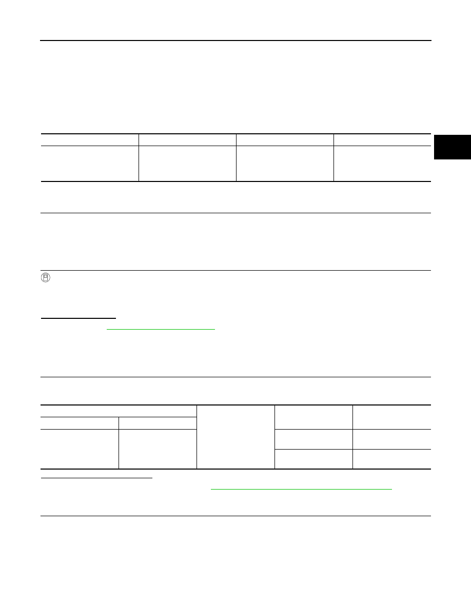
DTC Work Support
Item
Description
Check item
1ST GR FNCTN P0731
Following items for “1GR incorrect ratio” can be confirmed.
• Self-diagnosis status (whether the diagnosis is being performed or not)
• Self-diagnostic results (OK or NG)
• Input clutch solenoid
valve
• Front brake solenoid
valve
• Direct clutch solenoid
valve
• High and low reverse
clutch solenoid valve
• Low brake solenoid
valve
• 2346 brake solenoid
valve
• Anti-interlock sole-
noid valve
• Output speed sensor
• Input speed sensor 1,
2
• Each clutch and brake
• Hydraulic control cir-
cuit
2ND GR FNCTN P0732
Following items for “2GR incorrect ratio” can be confirmed.
• Self-diagnosis status (whether the diagnosis is being performed or not)
• Self-diagnostic results (OK or NG)
3RD GR FNCTN P0733
Following items for “3GR incorrect ratio” can be confirmed.
• Self-diagnosis status (whether the diagnosis is being performed or not)
• Self-diagnostic results (OK or NG)
4TH GR FNCTN P0734
Following items for “4GR incorrect ratio” can be confirmed.
• Self-diagnosis status (whether the diagnosis is being performed or not)
• Self-diagnostic results (OK or NG)
5TH GR FNCTN P0735
Following items for “5GR incorrect ratio” can be confirmed.
• Self-diagnosis status (whether the diagnosis is being performed or not)
• Self-diagnostic results (OK or NG)
6TH GR FNCTN P0729
Following items for “6GR incorrect ratio” can be confirmed.
• Self-diagnosis status (whether the diagnosis is being performed or not)
• Self-diagnostic results (OK or NG)
7TH GR FNCTN P1734
Following items for “7GR incorrect ratio” can be confirmed.
• Self-diagnosis status (whether the diagnosis is being performed or not)
• Self-diagnostic results (OK or NG)
TCC SOL FNCTN CHECK
Following items for “TCC solenoid function” can be confirmed.
• Self-diagnosis status (whether the diagnosis is being performed or not)
• Self-diagnostic results (OK or NG)
• Harness or connec-
tors
• Torque converter
clutch solenoid valve
• Torque converter
• Input speed sensor 1,
2
• Hydraulic control cir-
cuit

TM-68
< DTC/CIRCUIT DIAGNOSIS >
[7AT: RE7R01A (VQ35HR)]
U1000 CAN COMM CIRCUIT
DTC/CIRCUIT DIAGNOSIS
U1000 CAN COMM CIRCUIT
Description
INFOID:0000000005250024
CAN (Controller Area Network) is a serial communication line for real-time application. It is an on-vehicle mul-
tiplex communication line with high data communication speed and excellent malfunction detection ability.
Many electronic control units are equipped onto a vehicle, and each control unit shares information and links
with other control units during operation (not independently). In CAN communication, control units are con-
nected with 2 communication lines (CAN-H line, CAN-L line) allowing a high rate of information transmission
with less wiring. Each control unit transmits/receives data but selectively reads required data only.
DTC Logic
INFOID:0000000005250025
DTC DETECTION LOGIC
DTC CONFIRMATION PROCEDURE
1.
PRECONDITIONING
If “DTC CONFIRMATION PROCEDURE” has been previously conducted, always turn ignition switch OFF and
wait at least 10 seconds before conducting the next test.
>> GO TO 2.
2.
CHECK DTC DETECTION
With CONSULT-III
1.
Start the engine.
2.
Run engine for at least 2 consecutive seconds at idle speed.
3.
Perform “Self Diagnostic Results” in “TRANSMISSION”.
With GST
Follow the procedure “With CONSULT-III”
Is “U1000” detected?
YES
>> Go to
NO
>> INSPECTION END
Diagnosis Procedure
INFOID:0000000005250026
Go to
LAN-20, "Trouble Diagnosis Flow Chart"
.
DTC
Trouble diagnosis name
DTC is detected if...
Possible cause
U1000
CAN Communication Line
TCM cannot transmit or receive
CAN communication signals
continuously for 2 seconds or
more when the ignition switch is
ON.
• Harness or connectors
(CAN communication line is
open or shorted.)
• TCM
P0615 STARTER RELAY
TM-69
< DTC/CIRCUIT DIAGNOSIS >
[7AT: RE7R01A (VQ35HR)]
C
E
F
G
H
I
J
K
L
M
A
B
TM
N
O
P
P0615 STARTER RELAY
Description
INFOID:0000000005250027
TCM prohibits cranking other than at “P” or “N” position.
DTC Logic
INFOID:0000000005250028
DTC DETECTION LOGIC
DTC CONFIRMATION PROCEDURE
1.
PRECONDITIONING
If “DTC CONFIRMATION PROCEDURE” has been previously conducted, always turn ignition switch OFF and
wait at least 10 seconds before conducting the next test.
>> GO TO 2.
2.
CHECK DTC DETECTION
With CONSULT-III
1.
Shift the selector lever to “P” and “N” positions.
2.
Turn ignition switch ON and wait 2 seconds or more.
3.
Perform “Self Diagnostic Results” in “TRANSMISSION”.
Is “P0615” detected?
YES
>> Go to
NO
>> INSPECTION END
Diagnosis Procedure
INFOID:0000000005250029
1.
CHECK STARTER RELAY SIGNAL
1.
Turn ignition switch ON.
2.
Check voltage between IPDM E/R connector terminal and ground.
Is the inspection result normal?
YES
>> Check starter relay circuit. Refer to
STR-10, "Wiring Diagram - STARTING SYSTEM -"
NO
>> GO TO 2.
2.
CHECK HARNESS BETWEEN A/T ASSEMBLY AND IPDM E/R (PART 1)
1.
Turn ignition switch OFF.
2.
Disconnect A/T assembly connector and IPDM E/R connector.
3.
Check the continuity between A/T assembly vehicle side harness connector terminal and IPDM E/R vehi-
cle side harness connector terminal.
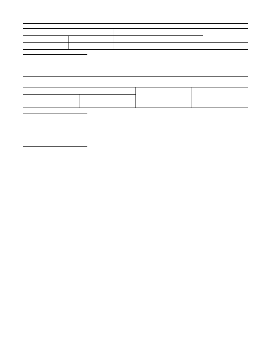
DTC
Trouble diagnosis name
DTC is detected if...
Possible cause
P0615
Starter Relay Circuit
The starter monitor value is
OFF when the ignition switch is
ON at the“ P” and “N” positions.
• Harness or connectors
(Starter relay and TCM circuit
is open or shorted.)
• Starter relay circuit
IPDM E/R connector
Ground
Condition
Voltage (Approx.)
Connector
Terminal
E5
30
Selector lever in “P” and
“N” positions.
Battery voltage
Selector lever in other
positions.
0 V
TM-70
< DTC/CIRCUIT DIAGNOSIS >
[7AT: RE7R01A (VQ35HR)]
P0615 STARTER RELAY
Is the inspection result normal?
YES
>> GO TO 3.
NO
>> Repair or replace damaged parts.
3.
CHECK HARNESS BETWEEN A/T ASSEMBLY AND IPDM E/R (PART 2)
Check the continuity between A/T assembly vehicle side harness connector terminal and ground.
Is the inspection result normal?
YES
>> GO TO 4.
NO
>> Repair or replace damaged parts.
4.
CHECK INTERMITTENT INCIDENT
GI-36, "Intermittent Incident"
Is the inspection result normal?
YES
>> Replace A/T assembly. Refer to
(2WD),
(AWD).
NO
>> Repair or replace damaged parts.
A/T assembly vehicle side harness connector
IPDM E/R vehicle side harness connector
Continuity
Connector
Terminal
Connector
Terminal
F51
9
E5
30
Existed
A/T assembly vehicle side harness connector
Ground
Continuity
Connector
Terminal
F51
9
Not existed
Нет комментариевНе стесняйтесь поделиться с нами вашим ценным мнением.
Текст