Infiniti FX35, FX50 (S51). Manual — part 864
P1217 ENGINE OVER TEMPERATURE
EC-997
< DTC/CIRCUIT DIAGNOSIS >
[VK50VE]
C
D
E
F
G
H
I
J
K
L
M
A
EC
N
P
O
>> Repair or replace malfunctioning part.
4.
CHECK RADIATOR CAP
Check radiator cap. Refer to
CO-37, "RADIATOR CAP : Inspection"
.
Is the inspection result normal?
YES
>> GO TO 5.
NO
>> Replace radiator cap.
5.
CHECK THERMOSTAT
Check thermostat. Refer to
Is the inspection result normal?
YES
>> GO TO 6.
NO
>> Replace thermostat
6.
CHECK ENGINE COOLANT TEMPERATURE SENSOR
EC-791, "Component Inspection"
Is the inspection result normal?
YES
>> GO TO 7.
NO
>> Replace engine coolant temperature sensor.
7.
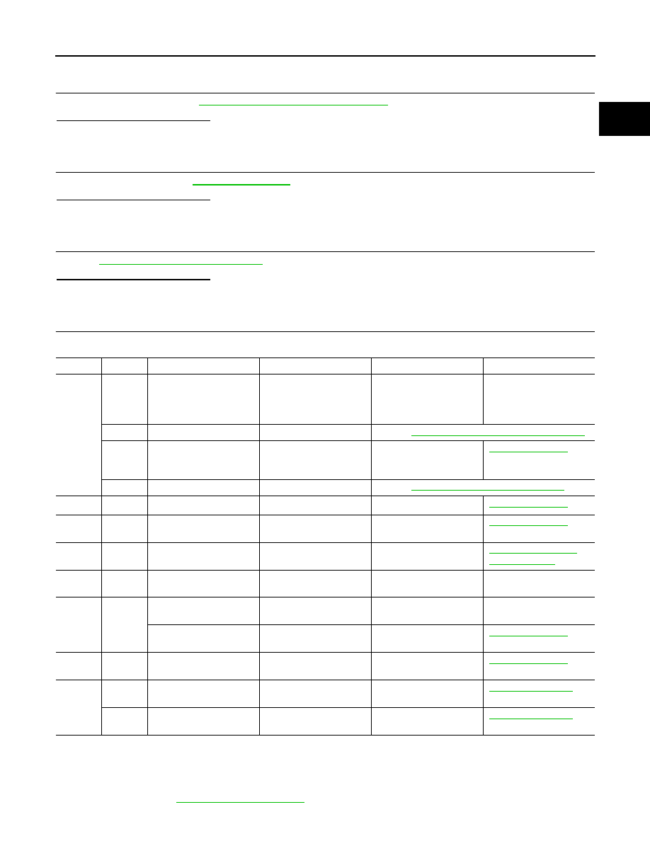
CHECK MAIN 12 CAUSES
If the cause cannot be isolated, check the following.
*1: Turn the ignition switch ON.
*2: Engine running at 3,000 rpm for 10 minutes.
*3: Drive at 90 km/h (56 MPH) for 30 minutes and then let idle for 10 minutes.
*4: After 60 minutes of cool down time.
For more information, refer to
CO-29, "Troubleshooting Chart"
.
Engine
Step
Inspection item
Equipment
Standard
Reference page
OFF
1
• Blocked radiator
• Blocked condenser
• Blocked radiator grille
• Blocked bumper
• Visual
No blocking
—
2
• Coolant mixture
• Coolant tester
Refer to
MA-13, "Anti-Freeze Coolant Mixture Ratio"
3
• Coolant level
• Visual
Coolant up to MAX level in
reservoir tank and radiator
filler neck
4
• Radiator cap
• Pressure tester
Refer to
CO-37, "RADIATOR CAP : Inspection"
.
ON*
2
5
• Coolant leakage
• Visual
No leakage
ON*
2
6
• Thermostat
• Touch the upper and
lower radiator hoses
Both hoses should be hot
ON*
1
7
• Cooling fan
• CONSULT-III
Operating
EC-995, "Component
Function Check"
OFF
8
• Combustion gas leak-
age
• Color checker chemical
tester 4 Gas analyzer
Negative
—
ON*
3
9
• Coolant temperature
gauge
• Visual
Gauge less than 3/4 when
driving
—
• Coolant overflow to res-
ervoir tank
• Visual
No overflow during driving
and idling
OFF*
4
10
• Coolant return from res-
ervoir tank to radiator
• Visual
Should be initial level in
reservoir tank
OFF
11
• Cylinder head
• Straight gauge feeler
gauge
0.1 mm (0.004 in) Maxi-
mum distortion (warping)
12
• Cylinder block and pis-
tons
• Visual
No scuffing on cylinder
walls or piston
EC-998
< DTC/CIRCUIT DIAGNOSIS >
[VK50VE]
P1217 ENGINE OVER TEMPERATURE
>> INSPECTION END

P1220 FUEL PUMP CONTROL MODULE (FPCM)
EC-999
< DTC/CIRCUIT DIAGNOSIS >
[VK50VE]
C
D
E
F
G
H
I
J
K
L
M
A
EC
N
P
O
P1220 FUEL PUMP CONTROL MODULE (FPCM)
Description
INFOID:0000000005237478
When driving conditions demand a decrease in fuel supply, the fuel
pump control module (FPCM) reduces the supply voltage to the fuel
pump. When driving conditions demand an increase in fuel supply
(during engine start, low engine coolant temperature or high load),
the supply voltage to the fuel pump is increased.
DTC Logic
INFOID:0000000005237479
DTC DETECTION LOGIC
DTC CONFIRMATION PROCEDURE
1.
PRECONDITIONING
If DTC Confirmation Procedure has been previously conducted, always perform the following procedure
before conducting the next test.
1.
Turn ignition switch OFF and wait at least 10 seconds.
2.
Turn ignition switch ON.
3.
Turn ignition switch OFF and wait at least 10 seconds.
TESTING CONDITION:
• Before performing the following procedure, confirm that battery voltage is between 12 - 15 V at idle.
• Before performing the following procedure, check that the engine coolant temperature is
−
10
°
C
(14
°
F) or more.
>> GO TO 2.
2.
PERFORM DTC CONFIRMATION PROCEDURE
1.
Start engine and let it idle for at least 5 seconds.
If engine does not start, crank engine for at least 5 seconds.
2.
Check DTC.
Is DTC detected?
YES
>> Go to
NO
>> INSPECTION END
Diagnosis Procedure
INFOID:0000000005237480
1.
CHECK GROUND CONNECTION
1.
Turn ignition switch OFF.
2.
Check ground connection M95. Refer to Ground Inspection in
Is the inspection result normal?
YES
>> GO TO 2.
NO
>> Repair or replace ground connection.
NNBIB0006ZZ
DTC No.
Trouble diagnosis name
DTC detecting condition
Possible cause
P1220
Fuel pump control module
(FPCM)
During engine cranking, the signal voltage
of the FPCM to the ECM is too low.
• Harness or connectors
(FPCM circuit is open or shorted)
(Fuel pump circuit is open or shorted)
• FPCM

EC-1000
< DTC/CIRCUIT DIAGNOSIS >
[VK50VE]
P1220 FUEL PUMP CONTROL MODULE (FPCM)
2.
CHECK FPCM POWER SUPPLY CIRCUIT
1.
Turn ignition switch OFF.
2.
Disconnect FPCM harness connector.
3.
Turn ignition switch ON.
4.
Check the voltage between FPCM harness connector and ground.
Is the inspection result normal?
YES
>> GO TO 4.
NO
>> GO TO 3.
3.
DETECT MALFUNCTIONING PART
Check the following.
• Harness connectors B3, E121
• 15 A fuse (No.41)
• Harness for open or short between FPCM and IPDM E/R
>> Repair open circuit, short to ground or short to power in harness or connectors.
4.
CHECK FPCM GROUND CIRCUIT FOR OPEN AND SHORT
1.
Turn ignition switch OFF.
2.
Check the continuity between FPCM harness connector and ground.
3.
Also check harness for short to power.
Is the inspection result normal?
YES
>> GO TO 5.
NO
>> Repair open circuit or short to power in harness or connectors.
5.
CHECK FPCM INPUT AND OUTPUT CIRCUITS FOR OPEN AND SHORT
1.
Disconnect ECM harness connector.
2.
Check the continuity between FPCM harness connector and ECM harness connector.
3.
Also check harness for short to ground and short to power.
Is the inspection result normal?
YES
>> GO TO 7.
NO
>> GO TO 6.
6.
DETECT MALFUNCTIONING PART
Check the following.
• Harness connectors B1, M7
• Harness for open or short between FPCM and ECM
>> Repair open circuit, short to ground or short to power in harness or connectors.
FPCM
Ground
Voltage
Connector
Terminal
B31
10
Ground
Battery voltage
FPCM
Ground
Continuity
Connector
Terminal
B31
5
Ground
Existed
FPCM
ECM
Continuity
Connector
Terminal
Connector
Terminal
B31
8
M160
125
Existed
9
112
Нет комментариевНе стесняйтесь поделиться с нами вашим ценным мнением.
Текст