Infiniti FX35, FX50 (S51). Manual — part 695

P0453 EVAP CONTROL SYSTEM PRESSURE SENSOR
EC-321
< DTC/CIRCUIT DIAGNOSIS >
[VQ35HR]
C
D
E
F
G
H
I
J
K
L
M
A
EC
N
P
O
With CONSULT-III
1.
Start engine and warm it up to normal operating temperature.
2.
Turn ignition switch OFF and wait at least 10 seconds.
3.
Turn ignition switch ON.
4.
Turn ignition switch OFF and wait at least 10 seconds.
5.
Turn ignition switch ON.
6.
Select “DATA MONITOR” mode with CONSULT-III.
7.
Check that “FUEL T/TMP SE” is more than 0
°
C (32
°
F).
8.
Start engine and wait at least 20 seconds.
9.
Check 1st trip DTC.
With GST
1.
Start engine and warm it up to normal operating temperature.
2.
Set voltmeter probes to ECM harness connector terminals under the following conditions.
3.
Check that the voltage is less than 4.2 V.
4.
Turn ignition switch OFF and wait at least 10 seconds.
5.
Turn ignition switch ON.
6.
Turn ignition switch OFF and wait at least 10 seconds.
7.
Start engine and wait at least 20 seconds.
8.
Check 1st trip DTC.
Is 1st trip DTC detected?
YES
>> Go to
NO
>> INSPECTION END
Diagnosis Procedure
INFOID:0000000005236908
1.
CHECK GROUND CONNECTION
1.
Turn ignition switch OFF.
2.
Check ground connection M95. Refer to Ground Inspection in
Is the inspection result normal?
YES
>> GO TO 2.
NO
>> Repair or replace ground connection.
2.
CHECK CONNECTOR
1.
Disconnect EVAP control system pressure sensor harness connector.
2.
Check that water is not inside connectors.
Is the inspection result normal?
YES
>> GO TO 3.
NO
>> Repair or replace harness connector.
3.
CHECK EVAP CONTROL SYSTEM PRESSURE SENSOR POWER SUPPLY CIRCUIT-I
1.
Turn ignition switch ON.
2.
Check the voltage between EVAP control system pressure sensor harness connector and ground.
Is the inspection result normal?
YES
>> GO TO 10.
NO
>> GO TO 4.
ECM
Connector
+
–
Terminal
Terminal
M107
106
(Fuel tank temperature sensor signal)
128
EVAP control system pressure sensor
Ground
Voltage (V)
Connector
Terminal
B252
3
Ground
Approx. 5

EC-322
< DTC/CIRCUIT DIAGNOSIS >
[VQ35HR]
P0453 EVAP CONTROL SYSTEM PRESSURE SENSOR
4.
CHECK EVAP CONTROL SYSTEM PRESSURE SENSOR POWER SUPPLY CIRCUIT-II
1.
Turn ignition switch OFF.
2.
Disconnect ECM harness connector.
3.
Check the continuity between EVAP control system pressure sensor harness connector and ECM har-
ness connector.
Is the inspection result normal?
YES
>> GO TO 6.
NO
>> GO TO 5.
5.
DETECT MALFUNCTIONING PART
Check the following.
• Harness connectors B201, M117
• Harness for open between ECM and EVAP control system pressure sensor
>> Repair open circuit.
6.
CHECK SENSOR POWER SUPPLY CIRCUIT
Check harness for short to power and short to ground, between the following terminals.
Is the inspection result normal?
YES
>> GO TO 7.
NO
>> Repair short to ground or short to power in harness or connectors.
7.
CHECK COMPONENTS
Check the following.
• CKP sensor (Refer to
EC-271, "Component Inspection"
• CMP sensor (bank 2) (Refer to
EC-277, "Component Inspection"
.)
• EVT control position sensor (bank 2) (Refer to
EC-369, "Component Inspection"
• Battery current sensor (Refer to
EC-400, "Component Inspection"
.)
• Refrigerant pressure sensor (Refer to
Is the inspection result normal?
YES
>> GO TO 8.
NO
>> Replace malfunctioning component.
8.
CHECK APP SENSOR
EVAP control system pressure sensor
ECM
Continuity
Connector
Terminal
Connector
Terminal
B252
3
M107
107
Existed
ECM
Sensor
Connector
Terminal
Name
Connector
Terminal
F101
46
Crankshaft position (CKP) sensor
F2
1
F102
64
Camshaft position (CMP) sensor (bank
2)
F18
1
Exhaust valve timing (EVT) control posi-
tion sensor (bank 2)
F19
1
Battery current sensor
E21
1
M107
103
Accelerator pedal position (APP) sensor
E112
(Without ICC)
6
E116
(With ICC)
3
107
EVAP control system pressure sensor
B252
3
111
Refrigerant pressure sensor
E77
3

P0453 EVAP CONTROL SYSTEM PRESSURE SENSOR
EC-323
< DTC/CIRCUIT DIAGNOSIS >
[VQ35HR]
C
D
E
F
G
H
I
J
K
L
M
A
EC
N
P
O
EC-444, "Component Inspection"
Is the inspection result normal?
YES
>> GO TO 20.
NO
>> GO TO 9.
9.
REPLACE ACCELERATOR PEDAL ASSEMBLY
1.
Replace accelerator pedal assembly
2.
Go to
EC-445, "Special Repair Requirement"
.
>> INSPECTION END
10.
CHECK EVAP CONTROL SYSTEM PRESSURE SENSOR GROUND CIRCUIT FOR OPEN AND
SHORT
1.
Turn ignition switch OFF.
2.
Disconnect ECM harness connector.
3.
Check the continuity between EVAP control system pressure sensor harness connector and ECM har-
ness connector.
4.
Also check harness for short to ground and short to power.
Is the inspection result normal?
YES
>> GO TO 12.
NO
>> GO TO 11.
11.
DETECT MALFUNCTIONING PART
Check the following.
• Harness connectors B201, M117
• Harness for open or short between EVAP control system pressure sensor and ECM
>> Repair open circuit, short to ground or short to power in harness or connectors.
12.
CHECK EVAP CONTROL SYSTEM PRESSURE SENSOR INPUT SIGNAL CIRCUIT FOR OPEN AND
SHORT
1.
Check the continuity between EVAP control system pressure sensor harness connector and ECM har-
ness connector.
2.
Also check harness for short to ground and short to power.
Is the inspection result normal?
YES
>> GO TO 14.
NO
>> GO TO 13.
13.
DETECT MALFUNCTIONING PART
Check the following.
• Harness connectors B201, M117
• Harness for open or short between EVAP control system pressure sensor and ECM
>> Repair open circuit, short to ground or short to power in harness or connectors.
14.
CHECK RUBBER TUBE
1.
Disconnect rubber tube connected to EVAP canister vent control valve.
EVAP control system pressure sensor
ECM
Continuity
Connector
Terminal
Connector
Terminal
B252
1
M107
112
Existed
EVAP control system pressure sensor
ECM
Continuity
Connector
Terminal
Connector
Terminal
B252
2
M107
102
Existed
EC-324
< DTC/CIRCUIT DIAGNOSIS >
[VQ35HR]
P0453 EVAP CONTROL SYSTEM PRESSURE SENSOR
2.
Check the rubber tube for clogging.
Is the inspection result normal?
YES
>> GO TO 15.
NO
>> Clean the rubber tube using an air blower, repair or replace rubber tube.
15.
CHECK EVAP CANISTER VENT CONTROL VALVE
EC-305, "Component Inspection"
Is the inspection result normal?
YES
>> GO TO 16.
NO
>> Replace EVAP canister vent control valve.
16.
CHECK EVAP CONTROL SYSTEM PRESSURE SENSOR
EC-324, "Component Inspection"
Is the inspection result normal?
YES
>> GO TO 17.
NO
>> Replace EVAP control system pressure sensor.
17.
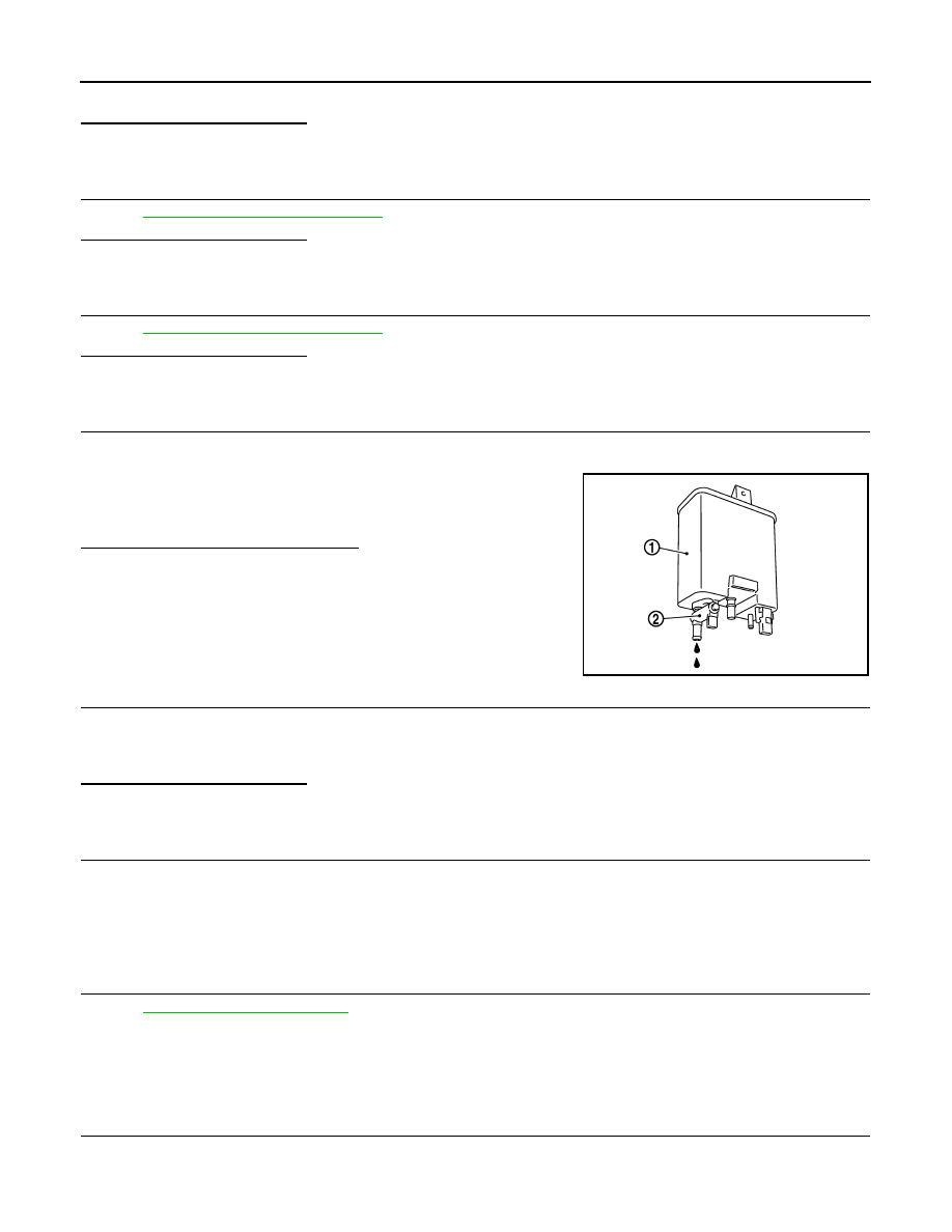
CHECK IF EVAP CANISTER IS SATURATED WITH WATER
1.
Remove EVAP canister with EVAP canister vent control valve and EVAP control system pressure sensor
attached.
2.
Check if water will drain from the EVAP canister (1).
Does water drain from EVAP canister?
YES
>> GO TO 18.
NO
>> GO TO 20.
18.
CHECK EVAP CANISTER
Weigh the EVAP canister with the EVAP canister vent control valve and EVAP control system pressure sensor
attached.
The weight should be less than 2.1 kg (4.6 lb).
Is the inspection result normal?
YES
>> GO TO 20.
NO
>> GO TO 19.
19.
DETECT MALFUNCTIONING PART
Check the following.
• EVAP canister for damage
• EVAP hose between EVAP canister and vehicle frame for clogging or poor connection
>> Repair hose or replace EVAP canister.
20.
CHECK INTERMITTENT INCIDENT
GI-36, "Intermittent Incident"
>> INSPECTION END
Component Inspection
INFOID:0000000005236909
1.
CHECK EVAP CONTROL SYSTEM PRESSURE SENSOR
1.
Turn ignition switch OFF.
2.
Remove EVAP control system pressure sensor with its harness connector connected from EVAP canister.
2
: EVAP canister vent control valve
PBIB2731E
Нет комментариевНе стесняйтесь поделиться с нами вашим ценным мнением.
Текст