Infiniti FX35, FX50 (S51). Manual — part 943
EM-72
< REMOVAL AND INSTALLATION >
[VQ35HR]
CAMSHAFT
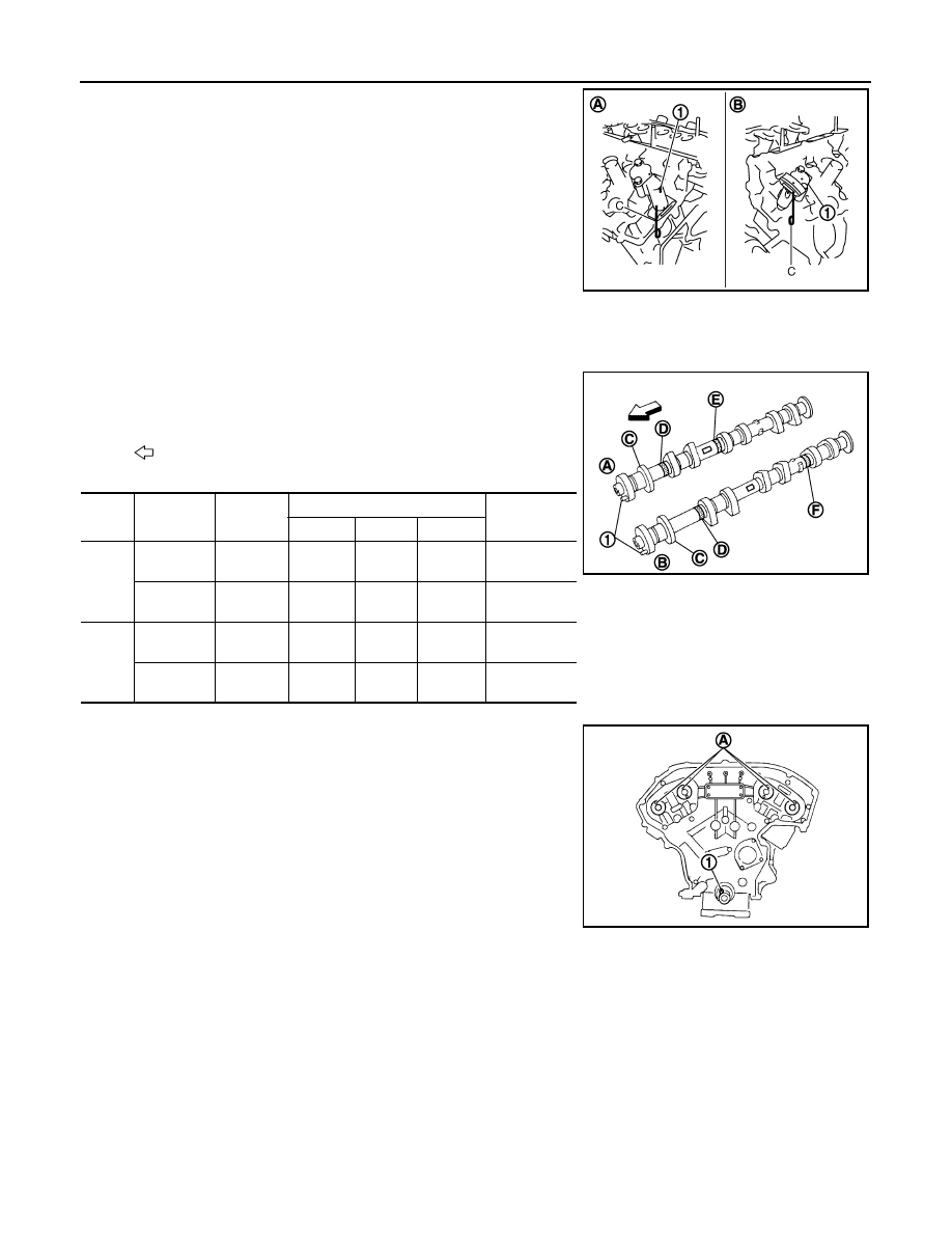
• Install timing chain tensioners (1) with its stopper pin (C)
attached.
2.
Install valve lifter.
• Install it in the original position.
3.
Install camshafts.
• Follow your identification marks made during removal, or fol-
low the identification marks that are present on new camshafts
for proper placement and direction.
• Install camshaft so that dowel pin (A) on front end face are
positioned as shown in the figure. (No. 1 cylinder TDC on its
compression stroke)
NOTE:
Though camshaft does not stop at the portion as shown in the
figure, for the placement of cam nose, it is generally accepted
camshaft is placed for the same direction of the figure.
Bank 1 side (A)
: Sliding part facing downward
Bank 2 side (B)
: Sliding part facing upward
JPBIA0121ZZ
: Engine front
Bank
INT/EXH
Dowel pin
(1)
Paint marks
Identification
mark (C)
M1 (E)
M2 (F)
M3 (D)
1
EXH (B)
Yes
No
Green
Light
blue
1F
INT (A)
Yes
Green
No
Light
blue
1E
2
INT (A)
Yes
Green
No
Light
blue
1G
EXH (B)
Yes
No
Green
Light
blue
1H
JPBIA1191ZZ
1
: Crankshaft key
JPBIA0094ZZ
CAMSHAFT
EM-73
< REMOVAL AND INSTALLATION >
[VQ35HR]
C
D
E
F
G
H
I
J
K
L
M
A
EM
N
P
O
4.
Install camshaft brackets.
• Remove foreign material completely from camshaft bracket
backside and from cylinder head installation face.
• Install camshaft bracket in original position and direction as
shown in figure.
• Install camshaft brackets (No. 2 to 4) aligning the stamp marks
(A) as shown in the figure.
NOTE:
There are no identification marks indicating bank 1 and bank 2
for camshaft bracket (No. 1).
• Apply liquid gasket to mating surface of camshaft bracket (No.
1) as shown on both bank 1 and bank 2.
Use Genuine RTV Silicone Sealant or an equivalent. Refer
to
GI-16, "Recommended Chemical Products and Seal-
A
: No. 1
B
: No. 2
C
: No. 3
D
: No. 4
E
: Camshaft brackets (bank 1)
F
: Exhaust side
G
: Intake side
H
: Camshaft brackets (bank 2)
I
: Intake side
J
: Exhaust side
: Engine front
JPBIA0258ZZ
B
: Bank 1
C
: Bank 2
: Engine front
JPBIA0272ZZ
a
: 8.5 mm (0.335 in)
b
: 2 mm (0.08 in)
c
: Clearance 5 mm (0.20 in)
d
:
φ
2.5 mm (0.098 in)
*
: Apply liquid gasket to rear timing chain side
JPBIA0255ZZ
EM-74
< REMOVAL AND INSTALLATION >
[VQ35HR]
CAMSHAFT
• Apply liquid gasket to camshaft bracket (No. 1) contact surface
on the rear timing chain case backside as shown on both bank
1 and bank 2.
Use Genuine RTV Silicone Sealant or an equivalent. Refer
to
GI-16, "Recommended Chemical Products and Seal-
.
CAUTION:
For camshaft bracket (No. 1) near installation position,
and install it without disturbing the liquid gasket applied
to the surfaces.
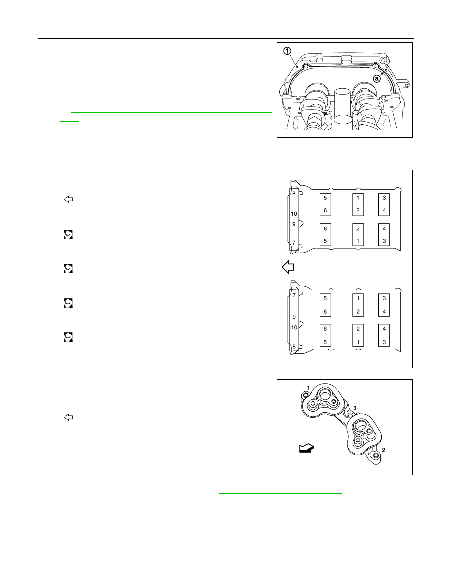
5.
Tighten camshaft bracket bolts in the following steps, in numeri-
cal order as shown in the figure.
a.
Tighten No. 7 to 10 in numerical order as shown.
b.
Tighten No. 1 to 6 in numerical order as shown.
c.
Tighten No. 1 to 10 in numerical order as shown.
d.
Tighten No. 1 to 10 in numerical order as shown.
6.
Install camshaft sensor bracket.
• Tighten camshaft sensor bracket bolts in numerical order as
shown in the figure.
NOTE:
The order of tightening bolts is the same for bank 1 and bank 2.
7.
Inspect and adjust the valve clearance. Refer to
EM-20, "Inspection and Adjustment"
.
8.
Install in the reverse order of removal after this step.
Inspection
INFOID:0000000005245151
INSPECTION AFTER REMOVAL
Camshaft Runout
1
: Rear timing chain case
a
:
φ
3.9 mm (0.154 in)
JPBIA0881ZZ
: Engine front
: 1.96 N·m (0.20 kg-m, 1 ft-lb)
: 1.96 N·m (0.20 kg-m, 1 ft-lb)
: 5.88 N·m (0.60 kg-m, 4 ft-lb)
: 10.4 N·m (1.1 kg-m, 8 ft-lb)
JPBIA0257ZZ
: Engine front
JPBIA1960ZZ

CAMSHAFT
EM-75
< REMOVAL AND INSTALLATION >
[VQ35HR]
C
D
E
F
G
H
I
J
K
L
M
A
EM
N
P
O
1.
Put V-block on precise flat table, and support No. 2 and 4 jour-
nals of camshaft.
CAUTION:
Never support No. 1 journal (on the side of camshaft
sprocket) because it has a different diameter from the other
three locations.
2.
Set a dial indicator vertically to No. 3 journal.
3.
Turn camshaft to one direction with hands, and measure the
camshaft runout on a dial indicator. (Total indicator reading)
4.
If it exceeds the limit, replace camshaft.
Camshaft Cam Height
1.
Measure the camshaft cam height with a micrometer.
2.
If wear exceeds the limit, replace camshaft.
Camshaft Journal Oil Clearance
CAMSHAFT JOURNAL DIAMETER
• Measure the outer diameter of camshaft journal with a micrometer
(A).
CAMSHAFT BRACKET INNER DIAMETER
• Tighten camshaft bracket bolt with the specified torque. Refer to “INSTALLATION” for the tightening proce-
dure.
• Measure inner diameter (A) of camshaft bracket with a bore gauge.
CAMSHAFT JOURNAL OIL CLEARANCE
• (Oil clearance) = (Camshaft bracket inner diameter) – (Camshaft journal diameter).
Standard and limit
: Refer to
PBIC0929E
Standard cam height
: Refer to
(Intake and exhaust)
Cam wear limit
: Refer to
EMQ0072D
Standard
: Refer to
JPBIA0122ZZ
Standard
: Refer to
.
PBIC1645E
Нет комментариевНе стесняйтесь поделиться с нами вашим ценным мнением.
Текст