Infiniti FX35, FX50 (S51). Manual — part 794
ON BOARD DIAGNOSTIC (OBD) SYSTEM
EC-717
< SYSTEM DESCRIPTION >
[VK50VE]
C
D
E
F
G
H
I
J
K
L
M
A
EC
N
P
O
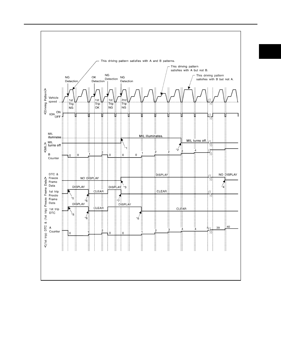
*1: When the same malfunction is de-
tected in two consecutive trips, MIL
will illuminate.
*2: MIL will turn off after vehicle is driven
3 times (pattern B) without any mal-
functions.
*3: When the same malfunction is de-
tected in two consecutive trips, the
DTC and the freeze frame data will be
stored in ECM.
JMBIA1418GB

EC-718
< SYSTEM DESCRIPTION >
[VK50VE]
ON BOARD DIAGNOSTIC (OBD) SYSTEM
Explanation for Driving Patterns Except for “Misfire <Exhaust Quality Deterioration>”, “Fuel Injection System”
<Driving Pattern A>
• The A counter will be cleared when the malfunction is detected regardless of (1) - (4).
• The A counter will be counted up when (1) - (4) are satisfied without the same malfunction.
• The DTC will not be displayed after the A counter reaches 40.
<Driving Pattern B>
Driving pattern B means operating vehicle as per following:
All components and systems should be monitored at least once by the OBD system.
• The B counter will be cleared when the malfunction is detected once regardless of the driving pattern.
• The B counter will be counted up when driving pattern B is satisfied without any malfunctions.
• The MIL will turn off when the B counter reaches 3 (*2 in OBD SYSTEM OPERATION CHART).
CONSULT-III Function
INFOID:0000000005237214
FUNCTION
*: The following emission-related diagnostic information is cleared when the ECM memory is erased.
• Diagnostic trouble codes
• 1st trip diagnostic trouble codes
• Freeze frame data
*4: The DTC and the freeze frame data
will not be displayed any longer after
vehicle is driven 40 times (pattern A)
without the same malfunction.
(The DTC and the freeze frame data
still remain in ECM.)
*5: When a malfunction is detected for
the first time, the 1st trip DTC and the
1st trip freeze frame data will be
stored in ECM.
*6: 1st trip DTC will be cleared after vehi-
cle is driven once (pattern B) without
the same malfunction.
*7: When the same malfunction is de-
tected in the 2nd trip, the 1st trip
freeze frame data will be cleared.
AEC574
Diagnostic test mode
Function
ECU Identification
ECM part number can be read.
Self Diagnostic Result
Self-diagnostic results such as 1st trip DTC, DTC and 1st trip freeze frame data or freeze frame data
can be read and erased quickly.*
Data Monitor
Input/Output data in the ECM can be read.
Active Test
Diagnostic Test Mode in which CONSULT-III drives some actuators apart from the ECM and also shifts
some parameters in a specified range.
Function Test
This mode is used to inform customers when the vehicle conditions require periodic maintenance.
Work Support
This mode enables a technician to adjust some devices faster and more accurately by following the in-
dications on the CONSULT-III screen.
DTC & SRT Confirmation
The status of system monitoring tests and the self-diagnosis status/results can be confirmed.
ON BOARD DIAGNOSTIC (OBD) SYSTEM
EC-719
< SYSTEM DESCRIPTION >
[VK50VE]
C
D
E
F
G
H
I
J
K
L
M
A
EC
N
P
O
• 1st trip freeze frame data
• System readiness test (SRT) codes
• Test values
SELF DIAGNOSTIC RESULT MODE
Self Diagnostic Item
Regarding items of DTC and 1st trip DTC, refer to
.
Freeze Frame Data and 1st Trip Freeze Frame Data
*: The items are the same as those of 1st trip freeze frame data.
DATA MONITOR MODE
Monitored Item
×
: Applicable
Freeze frame data item*
Description
DIAG TROUBLE CODE
[PXXXX]
• The engine control component part/control system has a trouble code that is displayed as PXXXX. (Refer
.)
CAL/LD VALUE [%]
• The calculated load value at the moment a malfunction is detected is displayed.
COOLANT TEMP
[
°
C] or [
°
F]
• The engine coolant temperature at the moment a malfunction is detected is displayed.
L-FUEL TRM-B1 [%]
• “Long-term fuel trim” at the moment a malfunction is detected is displayed.
• The “long-term fuel trim” indicates much more gradual feedback compensation to the base fuel schedule
than “short-term fuel trim”.
L-FUEL TRM-B2 [%]
S-FUEL TRM-B1 [%]
• “Short-term fuel trim” at the moment a malfunction is detected is displayed.
• The “short-term fuel trim” indicates dynamic or instantaneous feedback compensation to the base fuel
schedule.
S-FUEL TRM-B2 [%]
ENGINE SPEED [rpm]
• The engine speed at the moment a malfunction is detected is displayed.
VEHICL SPEED
[km/h] or [mph]
• The vehicle speed at the moment a malfunction is detected is displayed.
ABSOL TH·P/S [%]
• The throttle valve opening angle at the moment a malfunction is detected is displayed.
B/FUEL SCHDL [msec]
• The base fuel schedule at the moment a malfunction is detected is displayed.
INT/A TEMP SE
[
°
C] or [
°
F]
• The intake air temperature at the moment a malfunction is detected is displayed.
FUEL SYS-B1
• “Fuel injection system status” at the moment a malfunction is detected is displayed.
• One of the following mode is displayed.
Mode2: Open loop due to detected system malfunction
Mode3: Open loop due to driving conditions (power enrichment, deceleration enleanment)
Mode4: Closed loop - using oxygen sensor(s) as feedback for fuel control
Mode5: Open loop - has not yet satisfied condition to go to closed loop
FUEL SYS-B2
INT MANI PRES [kPa]
• These items are displayed but are not applicable to this model.
COMBUST CONDITION
Monitored item
Unit
Description
Remarks
ENG SPEED
rpm
• Indicates the engine speed computed from the
signal of the crankshaft position sensor and cam-
shaft position sensor.
• Accuracy becomes poor if engine
speed drops below the idle rpm.
• If the signal is interrupted while the
engine is running, an abnormal value
may be indicated.
MAS A/F SE-B1
V
• The signal voltage of the mass air flow sensor is
displayed.
• When the engine is stopped, a certain
value is indicated.
• When engine is running, specification
range is indicated in “SPEC”.
MAS A/F SE-B2
B/FUEL SCHDL
msec
• “Base fuel schedule” indicates the fuel injection
pulse width programmed into ECM, prior to any
learned on board correction.
• When engine is running, specification
range is indicated in “SPEC”.

EC-720
< SYSTEM DESCRIPTION >
[VK50VE]
ON BOARD DIAGNOSTIC (OBD) SYSTEM
A/F ALPHA-B1
%
• The mean value of the air-fuel ratio feedback cor-
rection factor per cycle is indicated.
• When the engine is stopped, a certain
value is indicated.
• This data also includes the data for
the air-fuel ratio learning control.
• When engine is running, specification
range is indicated in “SPEC”.
A/F ALPHA-B2
COOLAN TEMP/S
°
C or
°
F
• The engine coolant temperature (determined by
the signal voltage of the engine coolant tempera-
ture sensor) is displayed.
• When the engine coolant temperature
sensor is open or short-circuited,
ECM enters fail-safe mode. The en-
gine coolant temperature determined
by the ECM is displayed.
A/F SEN1 (B1)
V
• The A/F signal computed from the input signal of
the air fuel ratio (A/F) sensor 1 is displayed.
A/F SEN1 (B2)
HO2S2 (B1)
V
• The signal voltage of the heated oxygen sensor 2
is displayed.
HO2S2 (B2)
HO2S2 MNTR (B1)
RICH/LEAN
• Display of heated oxygen sensor 2 signal:
RICH: means the amount of oxygen after three
way catalyst is relatively small.
LEAN: means the amount of oxygen after three
way catalyst is relatively large.
• When the engine is stopped, a certain
value is indicated.
HO2S2 MNTR (B2)
VHCL SPEED SE
km/h or mph
• The vehicle speed computed from the vehicle
speed signal sent from unified meter and A/C
amp. is displayed.
BATTERY VOLT
V
• The power supply voltage of ECM is displayed.
ACCEL SEN 1
V
• The accelerator pedal position sensor signal volt-
age is displayed.
• ACCEL SEN 2 signal is converted by
ECM internally. Thus, they differs
from ECM terminal voltage signal.
ACCEL SEN 2
TP SEN 1-B1
V
• The throttle position sensor signal voltage is dis-
played.
• TP SEN 2-B1 signal is converted by
ECM internally. Thus, they differs
from ECM terminal voltage signal.
TP SEN 2-B1
FUEL T/TMP SE
°
C or
°
F
• The fuel temperature (determined by the signal
voltage of the fuel tank temperature sensor) is
displayed.
EVAP SYS PRES
V
• The signal voltage of EVAP control system pres-
sure sensor is displayed.
FUEL LEVEL SE
V
• The signal voltage of the fuel level sensor is dis-
played.
START SIGNAL
ON/OFF
• Indicates start signal status [ON/OFF] computed
by the ECM according to the signals of engine
speed and battery voltage.
• After starting the engine, [OFF] is dis-
played regardless of the starter sig-
nal.
CLSD THL POS
ON/OFF
• Indicates idle position [ON/OFF] computed by
ECM according to the accelerator pedal position
sensor signal.
AIR COND SIG
ON/OFF
• Indicates [ON/OFF] condition of the air condition-
er switch as determined by the air conditioner sig-
nal.
PW/ST SIGNAL
ON/OFF
• [ON/OFF] condition of the power steering system
(determined by the signal voltage of the power
steering pressure sensor signal) is indicated.
LOAD SIGNAL
ON/OFF
• Indicates [ON/OFF] condition from the electrical
load signal.
ON: Rear window defogger switch is ON and/or
lighting switch is in 2nd position.
OFF: Both rear window defogger switch and light-
ing switch are OFF.
Monitored item
Unit
Description
Remarks
Нет комментариевНе стесняйтесь поделиться с нами вашим ценным мнением.
Текст