Infiniti FX35, FX50 (S51). Manual — part 754

ENGINE CONTROL SYSTEM SYMPTOMS
EC-557
< SYMPTOM DIAGNOSIS >
[VQ35HR]
C
D
E
F
G
H
I
J
K
L
M
A
EC
N
P
O
1 - 6: The numbers refer to the order of inspection.
Valve
mecha-
nism
Timing chain
5
5
5
5
5
5
5
5
Camshaft
Intake valve timing control
Exhaust valve timing control
Intake valve
3
Exhaust valve
Exhaust
Exhaust manifold/Tube/Muffler/
Gasket
5
5
5
5
5
5
5
5
Three way catalyst
Lubrica-
tion
Oil pan/Oil strainer/Oil pump/Oil
filter/Oil gallery/Oil cooler
5
5
5
5
5
5
5
5
Oil level (Low)/Filthy oil
Cooling
Radiator/Hose/Radiator filler cap
5
5
5
5
5
5
5
4
5
Thermostat
5
Water pump
Water gallery
Cooling fan
5
Coolant level (Low)/Contaminat-
ed coolant
IVIS (INFINITI Vehicle Immobilizer System —
NATS)
1
1
SYMPTOM
Reference
page
HARD/NO S
T
A
R
T/RES
T
A
R
T (E
XCP
. HA)
E
N
GINE
ST
ALL
HES
IT
A
TION/SURGING/FLA
T
SPOT
S
P
ARK KNOC
K
/DET
O
NA
TI
ON
LACK OF
POWER/POOR ACCELERA
TION
HIG
H
IDL
E
/L
OW
ID
LE
ROUGH IDLE/HUNTING
ID
LING VI
BRA
T
ION
S
L
OW/NO RETU
RN
T
O ID
LE
OVERHEA
T
S
/W
A
TER TEMPERA
T
URE HIG
H
E
XCESSIVE
FUEL CON
S
UMP
T
ION
E
XCESSIVE
OIL
C
O
NSUMP
T
ION
B
A
TTER
Y
DEAD (UNDER CHARGE)
Warranty symptom code
AA
AB
AC
AD
AE
AF
AG
AH
AJ
AK
AL
AM
HA
EC-558
< SYMPTOM DIAGNOSIS >
[VQ35HR]
NORMAL OPERATING CONDITION
NORMAL OPERATING CONDITION
Description
INFOID:0000000005237128
FUEL CUT CONTROL (AT NO LOAD AND HIGH ENGINE SPEED)
If the engine speed is above 2,400 rpm under no load (for example, the selector lever position is neutral and
engine speed is over 2,400 rpm) fuel will be cut off after some time. The exact time when the fuel is cut off var-
ies based on engine speed.
Fuel cut will be operated until the engine speed reaches 1,500 rpm, then fuel cut will be cancelled.
NOTE:
This function is different from deceleration control listed under Multiport Fuel Injection (MFI) System,

PRECAUTIONS
EC-559
< PRECAUTION >
[VQ35HR]
C
D
E
F
G
H
I
J
K
L
M
A
EC
N
P
O
PRECAUTION
PRECAUTIONS
Precaution for Supplemental Restraint System (SRS) "AIR BAG" and "SEAT BELT
PRE-TENSIONER"
INFOID:0000000005525257
The Supplemental Restraint System such as “AIR BAG” and “SEAT BELT PRE-TENSIONER”, used along
with a front seat belt, helps to reduce the risk or severity of injury to the driver and front passenger for certain
types of collision. This system includes seat belt switch inputs and dual stage front air bag modules. The SRS
system uses the seat belt switches to determine the front air bag deployment, and may only deploy one front
air bag, depending on the severity of a collision and whether the front occupants are belted or unbelted.
Information necessary to service the system safely is included in the “SRS AIR BAG” and “SEAT BELT” of this
Service Manual.
WARNING:
• To avoid rendering the SRS inoperative, which could increase the risk of personal injury or death in
the event of a collision which would result in air bag inflation, all maintenance must be performed by
an authorized NISSAN/INFINITI dealer.
• Improper maintenance, including incorrect removal and installation of the SRS, can lead to personal
injury caused by unintentional activation of the system. For removal of Spiral Cable and Air Bag
Module, see the “SRS AIR BAG”.
• Do not use electrical test equipment on any circuit related to the SRS unless instructed to in this
Service Manual. SRS wiring harnesses can be identified by yellow and/or orange harnesses or har-
ness connectors.
PRECAUTIONS WHEN USING POWER TOOLS (AIR OR ELECTRIC) AND HAMMERS
WARNING:
• When working near the Air Bag Diagnosis Sensor Unit or other Air Bag System sensors with the
ignition ON or engine running, DO NOT use air or electric power tools or strike near the sensor(s)
with a hammer. Heavy vibration could activate the sensor(s) and deploy the air bag(s), possibly
causing serious injury.
• When using air or electric power tools or hammers, always switch the ignition OFF, disconnect the
battery, and wait at least 3 minutes before performing any service.
Precaution for Procedure without Cowl Top Cover
INFOID:0000000005237130
When performing the procedure after removing cowl top cover, cover
the lower end of windshield with urethane, etc.
Precautions For Xenon Headlamp Service
INFOID:0000000005237131
WARNING:
Comply with the following warnings to prevent any serious accident.
• Disconnect the battery cable (negative terminal) or the power supply fuse before installing, remov-
ing, or touching the xenon headlamp (bulb included). The xenon headlamp contains high-voltage
generated parts.
• Never work with wet hands.
• Check the xenon headlamp ON-OFF status after assembling it to the vehicle. Never turn the xenon
headlamp ON in other conditions. Connect the power supply to the vehicle-side connector.
(Turning it ON outside the lamp case may cause fire or visual impairments.)
• Never touch the bulb glass immediately after turning it OFF. It is extremely hot.
PIIB3706J
EC-560
< PRECAUTION >
[VQ35HR]
PRECAUTIONS
CAUTION:
Comply with the following cautions to prevent any error and malfunction.
• Install the xenon bulb securely. (Insufficient bulb socket installation may melt the bulb, the connec-
tor, the housing, etc. by high-voltage leakage or corona discharge.)
• Never perform HID circuit inspection with a tester.
• Never touch the xenon bulb glass with hands. Never put oil and grease on it.
• Dispose of the used xenon bulb after packing it in thick vinyl without breaking it.
• Never wipe out dirt and contamination with organic solvent (thinner, gasoline, etc.).
On Board Diagnostic (OBD) System of Engine and A/T
INFOID:0000000005237132
The ECM has an on board diagnostic system. It will illuminate the malfunction indicator lamp (MIL) to warn the
driver of a malfunction causing emission deterioration.
CAUTION:
• Always turn the ignition switch OFF and disconnect the negative battery cable before any repair or
inspection work. The open/short circuit of related switches, sensors, solenoid valves, etc. will cause
the MIL to illuminate.
• Always connect and lock the connectors securely after work. A loose (unlocked) connector will
cause the MIL to illuminate due to the open circuit. (Be sure the connector is free from water, grease,
dirt, bent terminals, etc.)
• Certain systems and components, especially those related to OBD, may use a new style slide-lock-
ing type harness connector. For description and how to disconnect, refer to
• Always route and secure the harnesses properly after work. The interference of the harness with a
bracket, etc. may cause the MIL to illuminate due to the short circuit.
• Always connect rubber tubes properly after work. A misconnected or disconnected rubber tube may
cause the MIL to illuminate due to the malfunction of the EVAP system or fuel injection system, etc.
• Always erase the unnecessary malfunction information (repairs completed) from the ECM and TCM
(Transmission control module) before returning the vehicle to the customer.
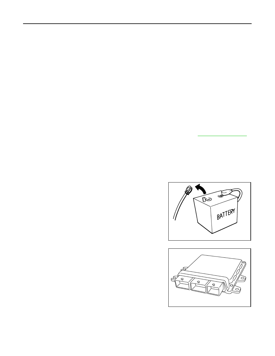
General Precautions
INFOID:0000000005237133
• Always use a 12 volt battery as power source.
• Never attempt to disconnect battery cables while engine is
running.
• Before connecting or disconnecting the ECM harness con-
nector, turn ignition switch OFF and disconnect negative bat-
tery cable. Failure to do so may damage the ECM because
battery voltage is applied to ECM even if ignition switch is
turned OFF.
• Before removing parts, turn ignition switch OFF and then dis-
connect battery ground cable.
• Never disassemble ECM.
• If a battery cable is disconnected, the memory will return to
the ECM value.
The ECM will now start to self-control at its initial value.
Engine operation can vary slightly when the terminal is dis-
connected. However, this is not an indication of a malfunc-
tion. Never replace parts because of a slight variation.
• If the battery is disconnected, the following emission-related
diagnostic information will be lost within 24 hours.
- Diagnostic trouble codes
- 1st trip diagnostic trouble codes
- Freeze frame data
- 1st trip freeze frame data
- System readiness test (SRT) codes
- Test values
SEF289H
JMBIA0057ZZ
Нет комментариевНе стесняйтесь поделиться с нами вашим ценным мнением.
Текст