Infiniti FX35, FX50 (S51). Manual — part 12
ADP-40
< SYSTEM DESCRIPTION >
AUTOMATIC DRIVE POSITIONER SYSTEM
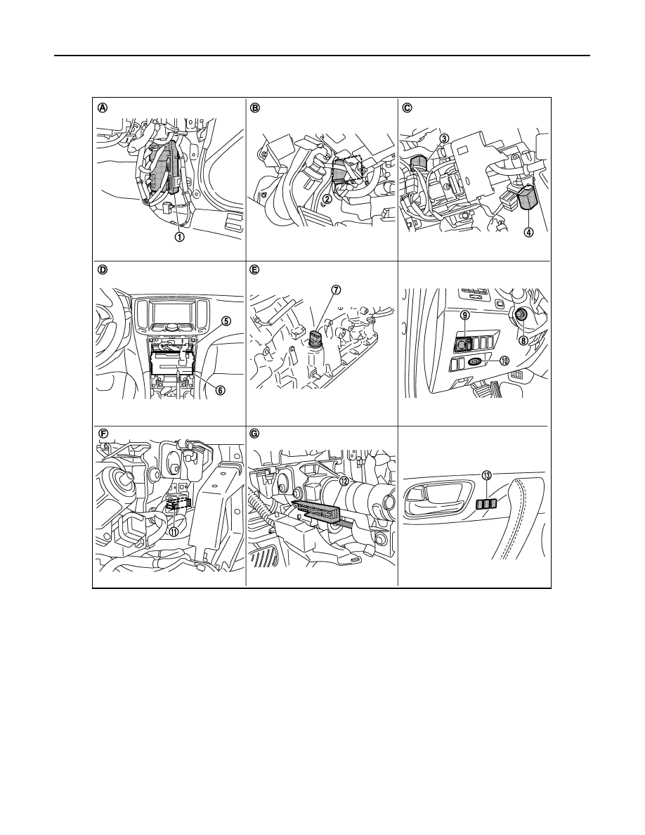
INTELLIGENT KEY INTERLOCK FUNCTION : Component Parts Location
INFOID:0000000005249649
1.
BCM M118, M119, M122, M123
2.
Automatic drive positioner control unit
M51, M52
3.
Tilt motor M49
4.
Telescopic motor M49
5.
Unified meter and A/C amp. M67
6.
AV control unit
With NAVI M87, M88
Without NAVI M83, M85
7.
AT assembly connector F51
8.
Tilt & telescopic switch M31
9.
Door mirror remote control switch
M26
10. Key slot M22
11.
Tilt sensor M48
12. Telescopic sensor M48
13. Seat memory switch D5
A.
Dash side lower (Passenger side)
B.
View with instrument driver lower
panel removed
C.
View with steering column cover low-
er and upper removed
D.
Behind cluster lid C
E.
A/T assembly
(TCM is built in A/T assembly)
F.
View with instrument driver lower
panel removed
G
View with steering column cover low-
er and upper removed
JMJIA1961ZZ
AUTOMATIC DRIVE POSITIONER SYSTEM
ADP-41
< SYSTEM DESCRIPTION >
C
D
E
F
G
H
I
K
L
M
A
B
ADP
N
O
P
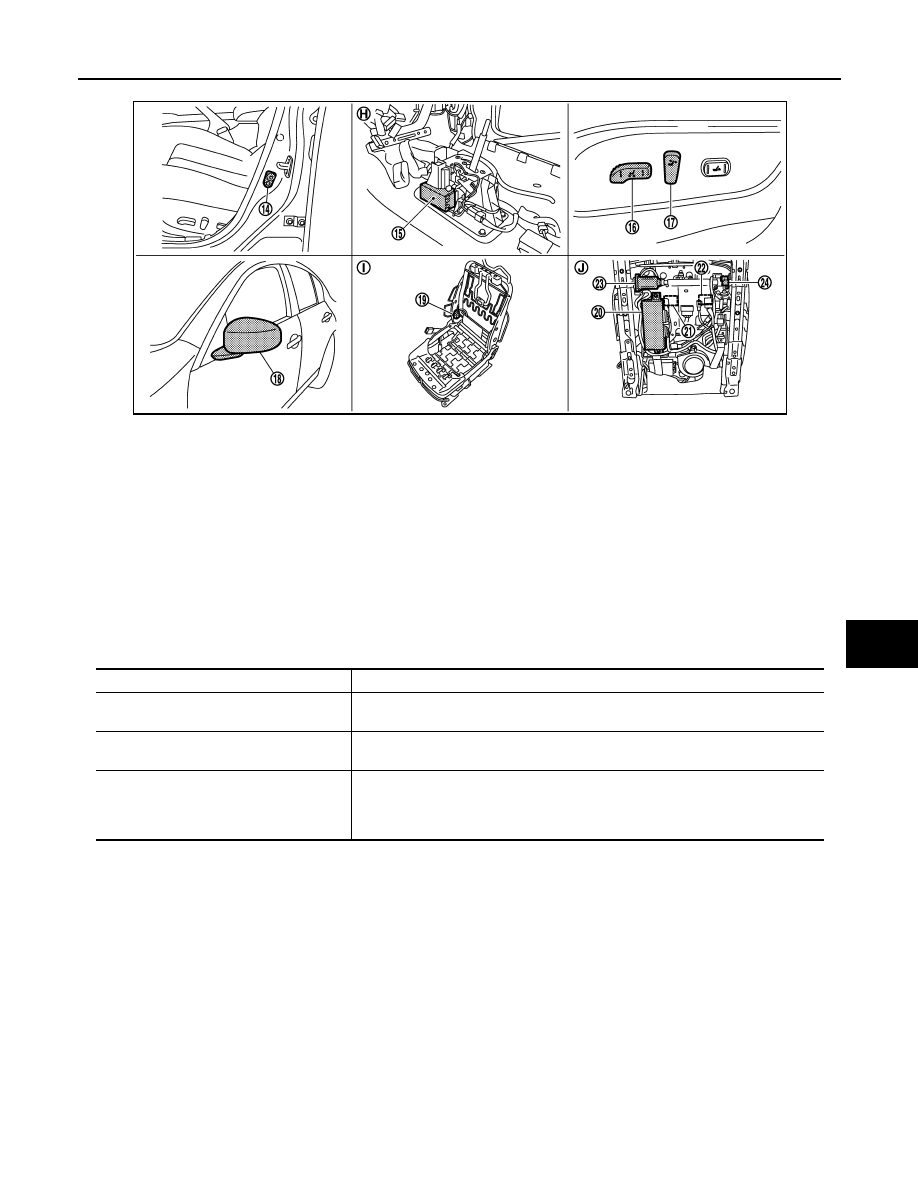
INTELLIGENT KEY INTERLOCK FUNCTION : Component Description
INFOID:0000000005249650
CONTROL UNITS
14. Front door switch (driver side) B16
15. A/T shift selector (detention switch)
M137
16. Sliding, lifting switch
(Power seat switch B459)
17. Reclining switch (power seat switch
B459)
18. Door mirror (driver side) D3
19. Reclining motor B454
20. Driver seat control unit B451, B452
21. Lifting motor (front) B455
22. Lifting motor (rear) B456
23. Sliding motor B461
24. Sliding sensor B453
H.
View with center console assembly
removed
I.
View with seat cushion pad and seat-
back pad removed
J.
Backside of the seat cushion
JMJIA1962ZZ
Item
Function
Driver seat control unit
It performs memory function and entry/exit assist function after receiving the door
unlock signal from BCM.
Automatic drive positioner control unit
Operates the steering column and door mirror with the instructions from the driver
seat control unit.
BCM
Recognizes the following status and transmits it to the driver seat control unit via
CAN communication.
• Door lock: UNLOCK
(with Intelligent Key or driver side door request switch)

ADP-42
< SYSTEM DESCRIPTION >
DIAGNOSIS SYSTEM (DRIVER SEAT C/U)
DIAGNOSIS SYSTEM (DRIVER SEAT C/U)
Diagnosis Description
INFOID:0000000005249651
The auto drive positioner system can be checked and diagnosed for component operation with CONSULT-III.
DIAGNOSTIC MODE
CONSULT-III Function
INFOID:0000000005249652
SELF-DIAGNOSIS RESULTS
DATA MONITOR
Diagnostic mode
[AUTO DRIVE POS.]
Description
WORK SUPPORT
Changes the setting of each function.
SELF-DIAG RESULTS
Performs self-diagnosis for the auto drive positioner system and displays the results.
DATA MONITOR
Displays input signals transmitted from various switches and sensors to driver seat con-
trol unit in real time.
CAN DIAG SUPPORT MNTR
The result of transmit/receive diagnosis of CAN communication can be read.
ACTIVE TEST
Drive each output device.
ECU PART NUMBER
Displays part numbers of driver seat control unit parts.
Monitor Item
Unit
Main
Signals
Selection
From
Menu
Contents
SET SW
“ON/OFF”
×
×
ON/OFF status judged from the setting switch signal.
MEMORY SW 1
“ON/OFF”
×
×
ON/OFF status judged from the seat memory switch 1 sig-
nal.
MEMORY SW 2
“ON/OFF”
×
×
ON/OFF status judged from the seat memory switch 2 sig-
nal.
SLIDE SW–FR
“ON/OFF”
×
×
ON/OFF status judged from the sliding switch (forward) sig-
nal.
SLIDE SW–RR
“ON/OFF”
×
×
ON/OFF status judged from the sliding switch (backward)
signal.
RECLN SW–FR
“ON/OFF”
×
×
ON/OFF status judged from the reclining switch (forward)
signal.
RECLN SW–RR
“ON/OFF”
×
×
ON/OFF status judged from the reclining switch (backward)
signal.
LIFT FR SW–UP
“ON/OFF”
×
×
ON/OFF status judged from the lifting switch front (up) sig-
nal.
LIFT FR SW–DN
“ON/OFF”
×
×
ON/OFF status judged from the lifting switch front (down)
signal.
LIFT RR SW–UP
“ON/OFF”
×
×
ON/OFF status judged from the lifting switch rear (up) sig-
nal.
LIFT RR SW–DN
“ON/OFF”
×
×
ON/OFF status judged from the lifting switch rear (down)
signal.
MIR CON SW–UP
“ON/OFF”
×
×
ON/OFF status judged from the mirror switch (up) signal.
MIR CON SW–DN
“ON/OFF”
×
×
ON/OFF status judged from the mirror switch (down) signal.
MIR CON SW–RH
“ON/OFF”
×
×
ON/OFF status judged from the door mirror remote control
switch (passenger side) signal.
MIR CON SW–LH
“ON/OFF”
×
×
ON/OFF status judged from the door mirror remote control
switch (driver side) signal.

DIAGNOSIS SYSTEM (DRIVER SEAT C/U)
ADP-43
< SYSTEM DESCRIPTION >
C
D
E
F
G
H
I
K
L
M
A
B
ADP
N
O
P
ACTIVE TEST
CAUTION:
When driving vehicle, do not perform active test.
MIR CHNG SW–R
“ON/OFF”
×
×
ON/OFF status judged from the door mirror remote control
switch (switching to right) signal.
MIR CHNG SW–L
“ON/OFF”
×
×
ON/OFF status judged from the door mirror remote control
switch (switching to left) signal.
TILT SW-UP
“ON/OFF”
×
×
ON/OFF status judged from the tilt switch (up) signal.
TILT SW-DOWN
“ON/OFF”
×
×
ON/OFF status judged from the tilt switch (down) signal.
TELESCO SW-FR
“ON/OFF”
×
×
ON/OFF status judged from the telescoping switch (for-
ward) signal.
TELESCO SW-RR
“ON/OFF”
×
×
ON/OFF status judged from the telescoping switch (back-
ward) signal.
DETENT SW
“ON/OFF”
×
×
The selector lever position “OFF (P position) / ON (other
than P position)” judged from the detention switch signal.
STARTER SW
“ON/OFF”
×
×
Ignition key switch ON (START, ON) /OFF (ACC, OFF) sta-
tus judged from the ignition switch signal.
SLIDE PULSE
—
–
×
Value (32768) when battery connections are standard. If it
moves backward, the value increases. If it moves forward,
the value decreases.
RECLN PULSE
—
–
×
Value (32768) when battery connections are standard. If it
moves backward, the value increases. If it moves forward,
the value decreases.
LIFT FR PULSE
—
–
×
Value (32768) when battery connections are standard. If it
moves DOWN, the value increases. If it moves UP, the val-
ue decreases.
LIFT RR PULSE
—
–
×
Value (32768) when battery connections are standard. If it
moves DOWN, the value increases. If it moves UP, the val-
ue decreases.
MIR/SEN RH U–D
“V”
–
×
Voltage input from door mirror sensor (passenger side) up/
down is displayed.
MIR/SEN RH R–L
“V”
–
×
Voltage input from door mirror sensor (passenger side) left/
right is displayed.
MIR/SEN LH U–D
“V”
–
×
Voltage input from door mirror sensor (driver side) up/down
is displayed.
MIR/SEN LH R–L
“V”
–
×
Voltage input from door mirror sensor (driver side) left/right
is displayed.
TILT SEN
“V”
–
×
Voltage input from tilt sensor is displayed.
TELESCO SEN
“V”
–
×
Voltage input from telescopic sensor is displayed.
Monitor Item
Unit
Main
Signals
Selection
From
Menu
Contents
Test item
Description
SEAT SLIDE
Activates/deactivates the sliding motor.
SEAT RECLINING
Activates/deactivates the reclining motor.
SEAT LIFTER FR
Activates/deactivates the lifting motor (front).
SEAT LIFTER RR
Activates/deactivates the lifting motor (rear).
TILT MOTOR
Activates/deactivates the tilt motor.
TELESCO MOTOR
Activates/deactivates the telescopic motor.
MIRROR MOTOR RH
Activates/deactivates the mirror motor (passenger side).
Нет комментариевНе стесняйтесь поделиться с нами вашим ценным мнением.
Текст