Infiniti FX35, FX50 (S51). Manual — part 1423

PCS-50
< DTC/CIRCUIT DIAGNOSIS >
[POWER DISTRIBUTION SYSTEM]
B2553 IGNITION RELAY
B2553 IGNITION RELAY
Description
INFOID:0000000005240672
BCM turns ON the following relays to ignition power supply to each ECU when the ignition switch is turned
ON.
• Ignition relay (located in fuse block)
• Ignition relay (built into IPDM E/R)
• Blower relay
BCM checks any ignition relay ON request for consistency with the actual ignition relay operation status.
DTC Logic
INFOID:0000000005240673
DTC DETECTION LOGIC
DTC CONFIRMATION PROCEDURE
1.
PERFORM DTC CONFIRMATION PROCEDURE
1.
Turn ignition switch ON under the following conditions (start the engine), and wait for at least 2 seconds.
-
Selector lever is in the P or N position.
-
Do not depress brake pedal.
2.
Check “Self diagnostic result” with CONSULT-III.
Is DTC detected?
YES
>> Go to
NO
>> INSPECTION END
Diagnosis Procedure
INFOID:0000000005240674
1.
CHECK DTC WITH IPDM E/R
Check “Self diagnostic result” with CONSULT-III. Refer to
Is the inspection result normal?
YES
>> GO TO 2.
NO
>> Repair or replace malfunctioning parts.
2.
CHECK FUSE
Check that the following fuse is not blown.
Is the fuse blown?
YES
>> Replace the blown fuse after repairing the affected circuit if a fuse is blown.
NO
>> GO TO 3.
3.
CHECK IGNITION RELAY FEEDBACK INPUT
1.
Turn ignition switch OFF.
2.
Disconnect BCM connector.
3.
Check voltage between BCM harness connector and ground.
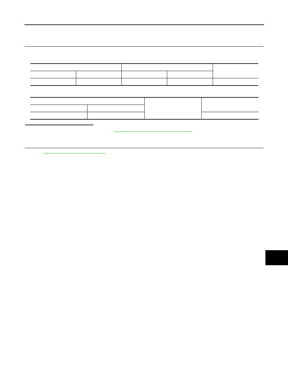
DTC No.
Trouble diagnosis name
DTC detecting condition
Possible cause
B2553
IGN POWER CIRCUIT
BCM detects a difference of signal for 2 seconds
or more between the following information.
• Ignition relay (fuse block) ON/OFF operation
• Ignition relay (fuse block) feedback.
• Harness or connectors
(Ignition relay feedback circuit is
open or short)
• Fuse
• Ignition relay
• IPDM E/R
Signal name
Connection position
Fuse No.
Capacity
Ignition power supply
IPDM E/R
44
10A

PCS
B2553 IGNITION RELAY
PCS-51
< DTC/CIRCUIT DIAGNOSIS >
[POWER DISTRIBUTION SYSTEM]
C
D
E
F
G
H
I
J
K
L
B
A
O
P
N
Is the inspection result normal?
YES
>> GO TO 5.
NO
>> GO TO 4.
4.
CHECK IGNITION RELAY FEEDBACK CIRCUIT
1.
Disconnect IPDM E/R connector.
2.
Check continuity between BCM harness connector and IPDM E/R harness connector.
3.
Check continuity between BCM harness connector and ground.
Is the inspection result normal?
YES
>> Replace IPDM E/R. Refer to
PCS-34, "Removal and Installation"
.
NO
>> Repair or replace harness.
5.
CHECK INTERMITTENT INCIDENT
GI-36, "Intermittent Incident"
.
>> INSPECTION END
(+)
(–)
Condition
Voltage (V)
(Approx.)
BCM
Connector
Terminal
M123
123
Ground
Ignition switch
OFF
0
ON
Battery voltage
BCM
IPDM E/R
Continuity
Connector
Terminal
Connector
Terminal
M123
123
E5
19
Existed
BCM
Ground
Continuity
Connector
Terminal
M123
123
Not existed

PCS-52
< DTC/CIRCUIT DIAGNOSIS >
[POWER DISTRIBUTION SYSTEM]
B260A IGNITION RELAY
B260A IGNITION RELAY
Description
INFOID:0000000005240675
When the ignition switch is turned ON, the BCM activates the following relays to provide power supply to each
ECU.
• Ignition relay (located in fuse block)
• Ignition relay (built into IPDM E/R)
• Blower relay
BCM checks any ignition relay ON request for consistency with the actual ignition relay operation status.
DTC Logic
INFOID:0000000005240676
DTC DETECTION LOGIC
NOTE:
• If DTC B260A is displayed with DTC U1000, first perform the trouble diagnosis for DTC U1000. Refer to
.
• If DTC B260A is displayed with DTC U1010, first perform the trouble diagnosis for DTC U1010. Refer to
.
• If DTC B260A is displayed with DTC B261A, first perform the trouble diagnosis for DTC B261A. Refer to
.
DTC CONFIRMATION PROCEDURE
1.
PERFORM DTC CONFIRMATION PROCEDURE
1.
Turn ignition switch ON under the following conditions, and wait for at least 2 seconds.
-
Selector lever is in the P or N position.
-
Do not depress brake pedal.
2.
Check “Self diagnostic result” with CONSULT-III.
Is DTC detected?
YES
>> Go to
NO
>> INSPECTION END
Diagnosis Procedure
INFOID:0000000005240677
1.
CHECK DTC WITH IPDM E/R
Check “Self diagnostic result” with CONSULT-III. Refer to
Is DTC detected?
YES
>> Repair or replace the malfunctioning parts.
NO
>> GO TO 2.
2.
CHECK IGNITION RELAY INPUT SIGNAL
1.
Turn ignition switch OFF.
2.
Disconnect BCM connector.
3.
Check voltage between BCM harness connector and ground.
Is the inspection result normal?
DTC No.
Trouble diagnosis
name
DTC detecting condition
Possible cause
B260A
IGNITION RELAY
BCM detects a difference of signal for 2 seconds or
more between the following information.
• Ignition relay (IPDM E/R) operation request
• Ignition relay feedback from IPDM E/R (CAN).
• Harness or connectors
(Ignition relay operation circuit is
open or shorted.)
• IPDM E/R
(+)
(–)
Voltage (V)
(Approx.)
BCM
Connector
Terminal
M121
47
Ground
Battery voltage
PCS
B260A IGNITION RELAY
PCS-53
< DTC/CIRCUIT DIAGNOSIS >
[POWER DISTRIBUTION SYSTEM]
C
D
E
F
G
H
I
J
K
L
B
A
O
P
N
YES
>> GO TO 4.
NO
>> GO TO 3.
3.
CHECK IGNITION RELAY (IPDM E/R) CIRCUIT
1.
Disconnect IPDM E/R connector.
2.
Check continuity between IPDM E/R harness connector and BCM harness connector.
3.
Check continuity between IPDM E/R harness connector and ground.
Is the inspection result normal?
YES
>> Replace IPDM E/R. Refer to
PCS-34, "Removal and Installation"
.
NO
>> Repair or replace harness.
4.
CHECK INTERMITTENT INCIDENT
GI-36, "Intermittent Incident"
.
>> INSPECTION END
IPDM E/R
BCM
Continuity
Connector
Terminal
Connector
Terminal
E5
27
M121
47
Existed
IPDM E/R
Ground
Continuity
Connector
Terminal
E5
27
Not existed
Нет комментариевНе стесняйтесь поделиться с нами вашим ценным мнением.
Текст