Infiniti FX35, FX50 (S51). Manual — part 489
BACK DOOR OPENER SWITCH OPERATION SIGNAL CIRCUIT
DLK-79
< DTC/CIRCUIT DIAGNOSIS >
C
D
E
F
G
H
I
J
L
M
A
B
DLK
N
O
P
BACK DOOR OPENER SWITCH OPERATION SIGNAL CIRCUIT
Description
INFOID:0000000005239563
BCM detects condition of the back door opener switch and transmits to back door control unit.
Component Function Check
INFOID:0000000005239564
1.
CHECK FUNCTION
Check back door opener switch (“TR/BD OPEN SW”) in “Data Monitor” mode using CONSULT-III.
Is the inspection result normal?
YES
>> Back door opener switch is OK.
NO
>> Refer to
.
Diagnosis Procedure
INFOID:0000000005239565
1.
CHECK BACK DOOR CONTROL UNIT INPUT SIGNAL
1.
Turn ignition switch OFF.
2.
Disconnect back door control unit.
3.
Check voltage between back door control unit harness connector and ground.
Is the inspection result normal?
YES
>> GO TO 4.
NO
>> GO TO 2.
2.
CHECK BACK DOOR CONTROL UNIT CIRCUIT
1.
Disconnect BCM connector.
2.
Check continuity between back door control unit harness connector and BCM harness connector.
3.
Check continuity between BCM harness connector and ground.
Is the inspection result normal?
YES
>> GO TO 3.
NO
>> Repair or replace harness.
3.
CHECK BCM OUTPUT SIGNAL
1.
Connect BCM connector.
2.
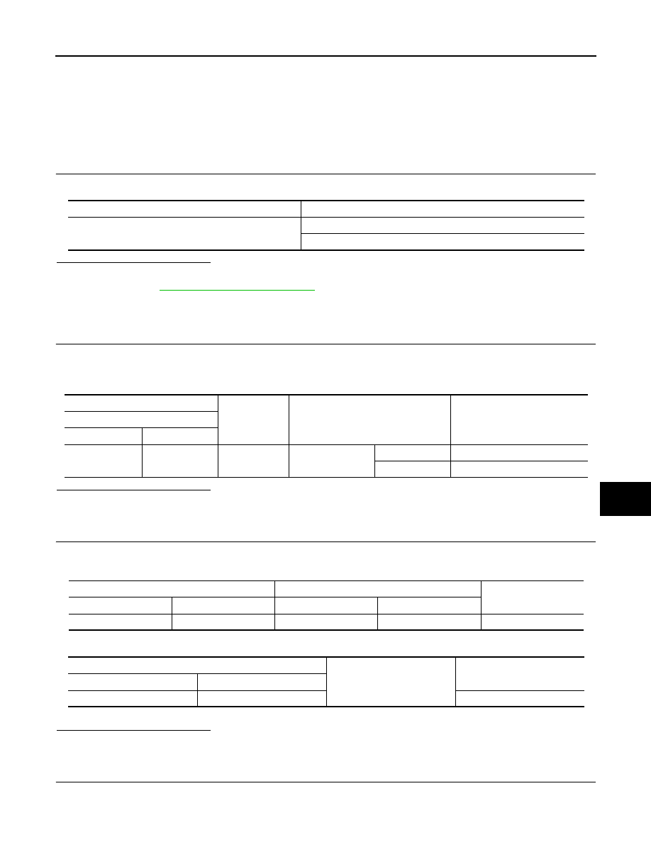
Check voltage between BCM harness connector and ground.
Monitor item
Condition
TR/BD OPEN SW
Back door opener switch is pressed: ON
Back door opener switch is released: OFF
(+)
(–)
Condition
Voltage (V)
(Approx.)
Back door control unit
Connector
Terminal
D123
6
Ground
Back door opener
switch
Not pressed
Battery voltage
Pressed
0
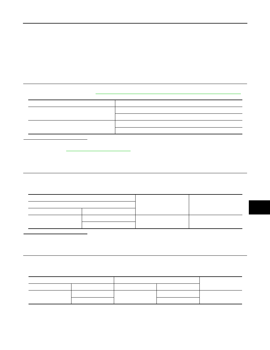
Back door control unit
BCM
Continuity
Connector
Terminal
Connector
Terminal
D123
6
M121
48
Existed
BCM
Ground
Continuity
Connector
Terminal
M121
48
Not existed

DLK-80
< DTC/CIRCUIT DIAGNOSIS >
BACK DOOR OPENER SWITCH OPERATION SIGNAL CIRCUIT
Is the inspection result normal?
YES
>> GO TO 4.
NO
>> Replace BCM. Refer to
BCS-83, "Removal and Installation"
4.
CHECK INTERMITTENT INCIDENT
GI-36, "Intermittent Incident"
.
>> INSPECTION END
(+)
(–)
Condition
Voltage (V)
(Approx.)
BCM
Connector
Terminal
M121
48
Ground
Back door opener
switch
Not pressed
Battery voltage
Pressed
0
KEY CYLINDER SWITCH
DLK-81
< DTC/CIRCUIT DIAGNOSIS >
C
D
E
F
G
H
I
J
L
M
A
B
DLK
N
O
P
KEY CYLINDER SWITCH
Description
INFOID:0000000005239566
Power window main switch detects condition of the door key cylinder switch and transmits to BCM as the
LOCK or UNLOCK signals.
Component Function Check
INFOID:0000000005239567
1.
CHECK DOOR KEY CYLINDER SWITCH INPUT SIGNAL
Check (“KEY CYL LK-SW”, “KEY CYL UN-SW”) in “DATA MONITOR” mode for “POWER DOOR LOCK SYS-
TEM” using CONSULT-III. Refer to
DLK-53, "DOOR LOCK : CONSULT-III Function (BCM - DOOR LOCK)"
.
Is the inspection result normal?
YES
>> Key cylinder switch is OK.
NO
>> Refer to
.
Diagnosis Procedure
INFOID:0000000005239568
1.
CHECK DOOR KEY CYLINDER SWITCH INPUT SIGNAL
1.
Turn ignition switch OFF.
2.
Disconnect front door lock assembly (driver side).
3.
Check voltage between front door lock assembly (driver side) harness connector and ground.
Is the inspection result normal?
YES
>> GO TO 3.
NO
>> GO TO 2.
2.
CHECK DOOR KEY CYLINDER SIGNAL CIRCUIT
1.
Disconnect power window main switch connector.
2.
Check continuity between power window main switch harness connector and front door lock assembly
(driver side) harness connector.
3.
Check continuity between power window main switch harness connector and ground.
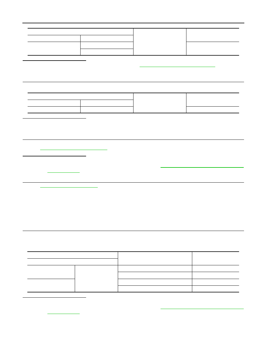
Monitor item
Condition
KEY CYL LK-SW
Lock
: ON
Neutral / Unlock
: OFF
KEY CYL UN-SW
Unlock
: ON
Neutral / Lock
: OFF
(+)
(–)
Voltage (V)
(Approx.)
Front door lock assembly (driver side)
Connector
Terminal
D15
5
Ground
5
6
Power window main switch
Front door lock assembly (driver side)
Continuity
Connector
Terminal
Connector
Terminal
D8
4
D15
6
Existed
6
5
DLK-82
< DTC/CIRCUIT DIAGNOSIS >
KEY CYLINDER SWITCH
Is the inspection result normal?
YES
>> Replace power window main switch. Refer to
PWC-136, "Removal and Installation"
NO
>> Repair or replace harness.
3.
CHECK DOOR KEY CYLINDER SWITCH GROUND CIRCUIT
Check continuity between front door lock assembly (driver side) harness connector and ground.
Is the inspection result normal?
YES
>> GO TO 4.
NO
>> Repair or replace harness.
4.
CHECK DOOR KEY CYLINDER SWITCH
Check door key cylinder switch.
Refer to
DLK-82, "Component Inspection"
Is the inspection result normal?
YES
>> GO TO 5.
NO
>> Replace front door lock assembly (driver side). Refer to
DLK-248, "DOOR ASSEMBLY : Removal
.
5.
CHECK INTERMITTENT INCIDENT
GI-36, "Intermittent Incident"
>> INSPECTION END
Component Inspection
INFOID:0000000005239569
COMPONENT INSPECTION
1.
CHECK DOOR KEY CYLINDER SWITCH
1.
Turn ignition switch OFF.
2.
Disconnect front door lock assembly (driver side) (key cylinder switch) terminals.
3.
Check front door lock assembly (driver side) (key cylinder switch) terminals.
Is the inspection result normal?
YES
>> Door key cylinder switch is OK.
NO
>> Replace front door lock assembly (driver side). Refer to
DLK-248, "DOOR ASSEMBLY : Removal
.
Power window main switch
Ground
Continuity
Connector
Terminal
D8
4
Not existed
6
Front door lock assembly (driver side)
Ground
Continuity
Connector
Terminal
D15
4
Existed
Terminal
Key position
Continuity
Front door lock assembly (driver side) connector
5
4
Unlock
Existed
Neutral / Lock
Not existed
6
Lock
Existed
Neutral / Unlock
Not existed
Нет комментариевНе стесняйтесь поделиться с нами вашим ценным мнением.
Текст