Infiniti FX35, FX50 (S51). Manual — part 1492
ENCODER
PWC-29
< DTC/CIRCUIT DIAGNOSIS >
[FRONT & REAR WINDOW ANTI-PINCH]
C
D
E
F
G
H
I
J
L
M
A
B
PWC
N
O
P
ENCODER
DRIVER SIDE
DRIVER SIDE : Description
INFOID:0000000005248178
Detects condition of the front power window motor (driver side) operation and transmits to power window main
switch as the pulse signal.
DRIVER SIDE : Component Function Check
INFOID:0000000005248179
1.
CHECK ENCODER
Check that driver side door glass performs AUTO open/close operation normally by power window main
switch.
Is the inspection result normal?
YES
>> Encoder is OK.
NO
>> Refer to
PWC-29, "DRIVER SIDE : Diagnosis Procedure"
DRIVER SIDE : Diagnosis Procedure
INFOID:0000000005248180
1.
CHECK ENCODER SIGNAL
1.
Turn ignition switch ON.
2.
Check signal between power window main switch harness connector and ground with oscilloscope.
Is the inspection result normal?
YES
>> Replace power window main switch. Refer to
PWC-136, "Removal and Installation"
NO
>> GO TO 2.
2.
CHECK ENCORDER SIGNAL CIRCUIT
1.
Turn ignition switch OFF.
2.
Disconnect power window main switch connector and front power window motor (driver side) connector.
3.
Check continuity between power window main switch harness connector and front power window motor
(driver side) harness connector.
4.
Check continuity between power window main switch harness connector and ground.
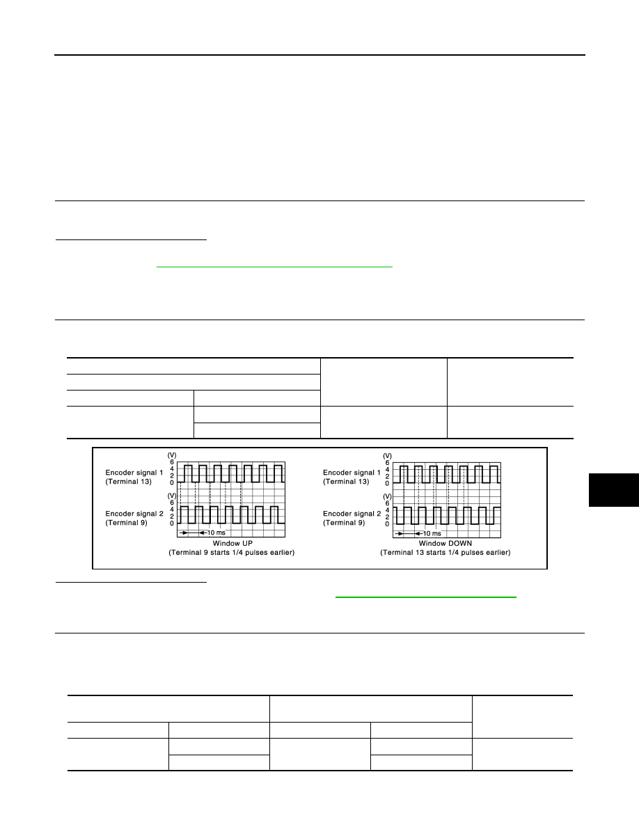
(+)
(–)
Signal
(Reference value)
Power window main switch
Connector
Terminal
D8
9
Ground
Refer to following signal
13
JMKIA2682GB
Power window main switch
Front power window motor
(driver side)
Continuity
Connector
Terminal
Connector
Terminal
D8
9
D10
3
Existed
13
5

PWC-30
< DTC/CIRCUIT DIAGNOSIS >
[FRONT & REAR WINDOW ANTI-PINCH]
ENCODER
Is the inspection result normal?
YES
>> GO TO 3.
NO
>> Repair or replace harness.
3.
CHECK ENCORDER POWER SUPPLY CIRCUIT 1
1.
Connect power window main switch connector.
2.
Turn ignition switch ON.
3.
Check voltage between front power window motor (driver side) harness connector and ground.
Is the inspection result normal?
YES
>> GO TO 5.
NO
>> GO TO 4.
4.
CHECK ENCORDER POWER SUPPLY CIRCUIT 2
1.
Turn ignition switch OFF.
2.
Disconnect power window main switch connector.
3.
Check continuity between power window main switch harness connector and front power window motor
(driver side) harness connector.
4.
Check continuity between power window main switch harness connector and ground.
Is the inspection result normal?
YES
>> Replace power window main switch. Refer to
PWC-136, "Removal and Installation"
NO
>> Repair or replace harness.
5.
CHECK GROUND CIRCUIT 1
1.
Turn ignition switch OFF.
2.
Check continuity between front power window motor (driver side) harness connector and ground.
Is the inspection result normal?
YES
>> Replace front power window motor (driver side). Refer to
GW-21, "Removal and Installation"
.
NO
>> GO TO 6.
6.
CHECK GROUND CIRCUIT 2
1.
Disconnect power window main switch connector.
Power window main switch
Ground
Continuity
Connector
Terminal
D8
9
Not existed
13
(+)
(–)
Voltage (V)
(Approx.)
Front power window motor (driver side)
Connector
Terminal
D10
4
Ground
Battery voltage
Power window main switch
Front power window motor (driver side)
Continuity
Connector
Terminal
Connector
Terminal
D8
15
D10
4
Existed
Power window main switch
Ground
Continuity
Connector
Terminal
D8
15
Not existed
Front power window motor (driver side)
Ground
Continuity
Connector
Terminal
D10
6
Existed
ENCODER
PWC-31
< DTC/CIRCUIT DIAGNOSIS >
[FRONT & REAR WINDOW ANTI-PINCH]
C
D
E
F
G
H
I
J
L
M
A
B
PWC
N
O
P
2.
Check continuity between power window main switch harness connector and front power window motor
(driver side) harness connector.
Is the inspection result normal?
YES
>> Replace power window main switch. Refer to
PWC-136, "Removal and Installation"
NO
>> Repair or replace harness.
PASSENGER SIDE
PASSENGER SIDE : Description
INFOID:0000000005248181
Detects condition of the front power window motor (passenger side) operation and transmits to front power
window switch (passenger side) as the pulse signal.
PASSENGER SIDE : Component Function Check
INFOID:0000000005248182
1.
CHECK ENCODER
Check that passenger side door glass performs AUTO open/close operation normally by power window main
switch or front power window switch (passenger side).
Is the inspection result normal?
YES
>> Encoder is OK.
NO
>> Refer to
PWC-31, "PASSENGER SIDE : Diagnosis Procedure"
.
PASSENGER SIDE : Diagnosis Procedure
INFOID:0000000005248183
1.
CHECK ENCODER SIGNAL
1.
Turn ignition switch ON.
2.
Check signal between front power window switch (passenger side) harness connector and ground with
oscilloscope.
Is the inspection result normal?
YES
>> Replace front power window switch (passenger side). Refer to
PWC-137, "Removal and Installa-
.
NO
>> GO TO 2.
2.
CHECK ENCORDER SIGNAL CIRCUIT
1.
Turn ignition switch OFF.
Power window main switch
Front power window motor (driver side)
Continuity
Connector
Terminal
Connector
Terminal
D8
2
D10
6
Existed
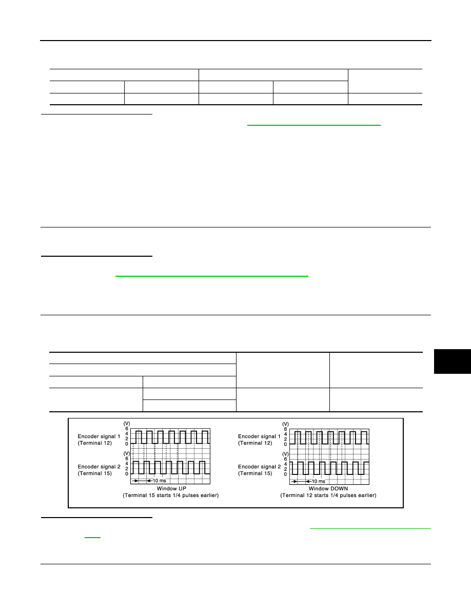
(+)
(–)
Signal
(Reference value)
Front power window switch (passenger side)
Connector
Terminal
D38
12
Ground
Refer to following signal
15
JMKIA2927GB

PWC-32
< DTC/CIRCUIT DIAGNOSIS >
[FRONT & REAR WINDOW ANTI-PINCH]
ENCODER
2.
Disconnect front power window switch (passenger side) connector and front power window motor (pas-
senger side) connector.
3.
Check continuity between front power window switch (passenger side) harness connector and front power
window motor (passenger side) harness connector.
4.
Check continuity between front power window switch (passenger side) harness connector and ground.
Is the inspection result normal?
YES
>> GO TO 3.
NO
>> Repair or replace harness.
3.
CHECK ENCORDER POWER SUPPLY CIRCUIT 1
1.
Connect front power window switch (passenger side) connector.
2.
Turn ignition switch ON.
3.
Check voltage between front power window motor (passenger side) harness connector and ground.
Is the inspection result normal?
YES
>> GO TO 4.
NO
>> GO TO 5.
4.
CHECK GROUND CIRCUIT 1
1.
Turn ignition switch OFF.
2.
Check continuity between front power window motor (passenger side) harness connector and ground.
Is the inspection result normal?
YES
>> Replace front power window motor (passenger side). Refer to
GW-21, "Removal and Installation"
.
NO
>> GO TO 6.
5.
CHECK ENCORDER POWER SUPPLY CIRCUIT 2
1.
Turn ignition switch OFF.
2.
Disconnect front power window switch (passenger side) connector.
3.
Check continuity between front power window switch (passenger side) harness connector and front power
window motor (passenger side) harness connector.
4.
Check continuity between front power window switch (passenger side) harness connector and ground.
Front power window switch (passenger side)
Front power window motor (passenger side)
Continuity
Connector
Terminal
Connector
Terminal
D38
12
D40
5
Existed
15
3
Front power window switch (passenger side)
Ground
Continuity
Connector
Terminal
D38
12
Not existed
15
(+)
(–)
Voltage (V)
(Approx.)
Front power window motor (passenger side)
Connector
Terminal
D40
4
Ground
Battery voltage
Front power window motor (passenger side)
Ground
Continuity
Connector
Terminal
D40
6
Existed
Front power window switch (passenger side)
Front power window motor (passenger side)
Continuity
Connector
Terminal
Connector
Terminal
D38
4
D40
4
Existed
Нет комментариевНе стесняйтесь поделиться с нами вашим ценным мнением.
Текст