Infiniti FX35, FX50 (S51). Manual — part 1432

PCS-86
< ECU DIAGNOSIS INFORMATION >
[POWER DISTRIBUTION SYSTEM]
BCM (BODY CONTROL MODULE)
Terminal No.
(Wire color)
Description
Condition
Value
(Approx.)
Signal name
Input/
Output
+
–
1
(W)
Ground
Battery power supply
Input
Ignition switch OFF
Battery voltage
2
(Y)
Ground
P/W power supply
(BAT)
Output
Ignition switch OFF
12 V
3
(O)
Ground
P/W power supply
(RAP)
Output
Ignition switch ON
12 V
4
(P)
Ground
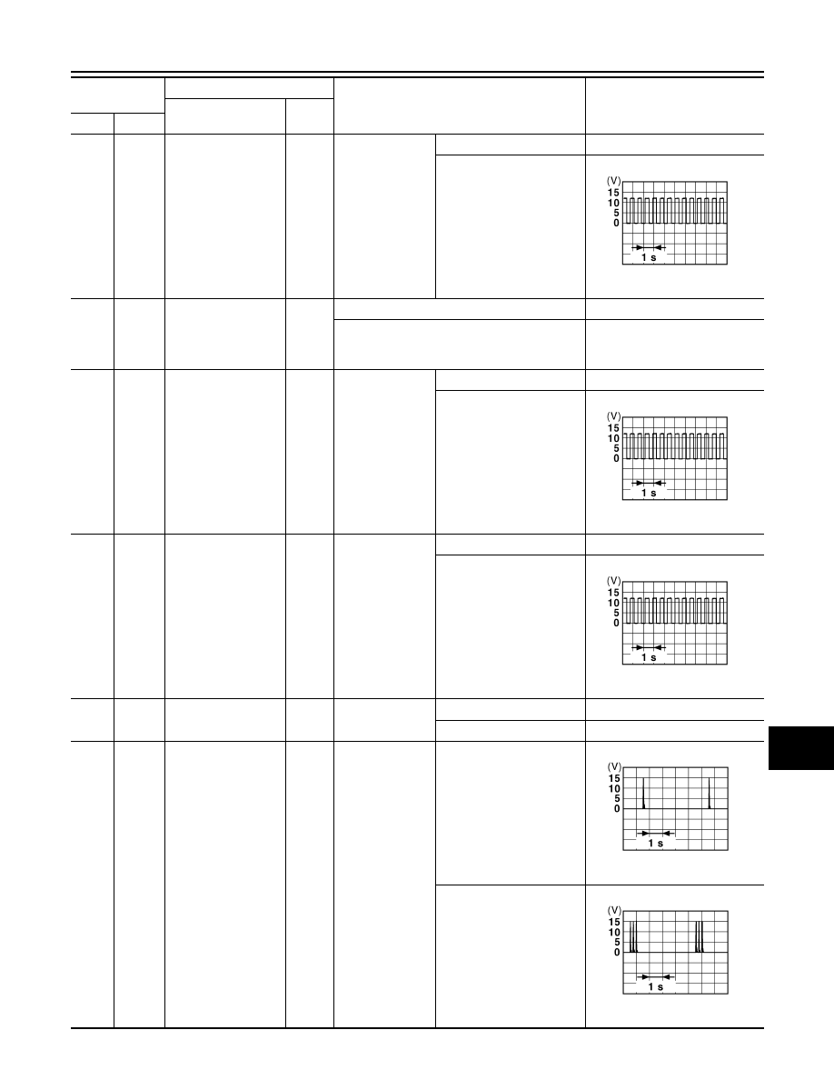
Interior room lamp
power supply
(Battery saver signal)
Output
Interior room lamp battery saver is activated.
(Cuts the interior room lamp power supply)
0 V
Interior room lamp battery saver is not activat-
ed.
(Outputs the interior room lamp power supply)
12 V
5
(V)
Ground
Passenger door UN-
LOCK
Output
Passenger door
UNLOCK
(Actuator is activated)
12 V
Other than UNLOCK
(Actuator is not activated)
0 V
7
(Y)
Ground
Step lamp
Output
Step lamp
ON
0 V
OFF
12 V
8
(V)
Ground
All doors, fuel lid
LOCK
Output
All doors, fuel lid
LOCK
(Actuator is activated)
12 V
Other than LOCK
(Actuator is not activated)
0 V
9
(G)
Ground
Driver door, fuel lid
UNLOCK
Output
Driver door, fuel
lid
UNLOCK
(Actuator is activated)
12 V
Other than UNLOCK
(Actuator is not activated)
0 V
10
(BR)
Ground
Rear RH door and
rear LH door UN-
LOCK
Output
Rear RH door
and rear LH door
UNLOCK
(Actuator is activated)
12 V
Other than UNLOCK
(Actuator is not activated)
0 V
11
(R)
Ground
Battery power supply
Input
Ignition switch OFF
Battery voltage
13
(B)
Ground
Ground
—
Ignition switch ON
0 V
15
(Y)
Ground
ACC indicator lamp
Output
Ignition switch
OFF (LOCK indicator is not
illuminated)
Battery voltage
ACC or ON
0 V
17
(W)
Ground
Turn signal RH
(Front)
Output
Ignition switch
ON
Turn signal switch OFF
0 V
Turn signal switch RH
6.5 V
PKID0926E
PCS
BCM (BODY CONTROL MODULE)
PCS-87
< ECU DIAGNOSIS INFORMATION >
[POWER DISTRIBUTION SYSTEM]
C
D
E
F
G
H
I
J
K
L
B
A
O
P
N
18
(O)
Ground
Turn signal LH
(Front)
Output
Ignition switch
ON
Turn signal switch OFF
0 V
Turn signal switch LH
6.5 V
19
(SB)
Ground
Room lamp timer
Output
Other than under condition
5.0 V
• Interior room lamp timer is activated.
(Door is unlocked. etc...)
• Welcome light function is activated.
0 V
20
(V)
Ground
Turn signal RH
(Rear)
Output
Ignition switch
ON
Turn signal switch OFF
0 V
Turn signal switch RH
6.5 V
25
(G)
Ground
Turn signal LH (Rear)
Output
Ignition switch
ON
Turn signal switch OFF
0 V
Turn signal switch LH
6.5 V
26
(P)
Ground
Rear wiper
Output
Rear wiper
OFF (Stopped)
0 V
ON (Operated)
12 V
34
(SB)
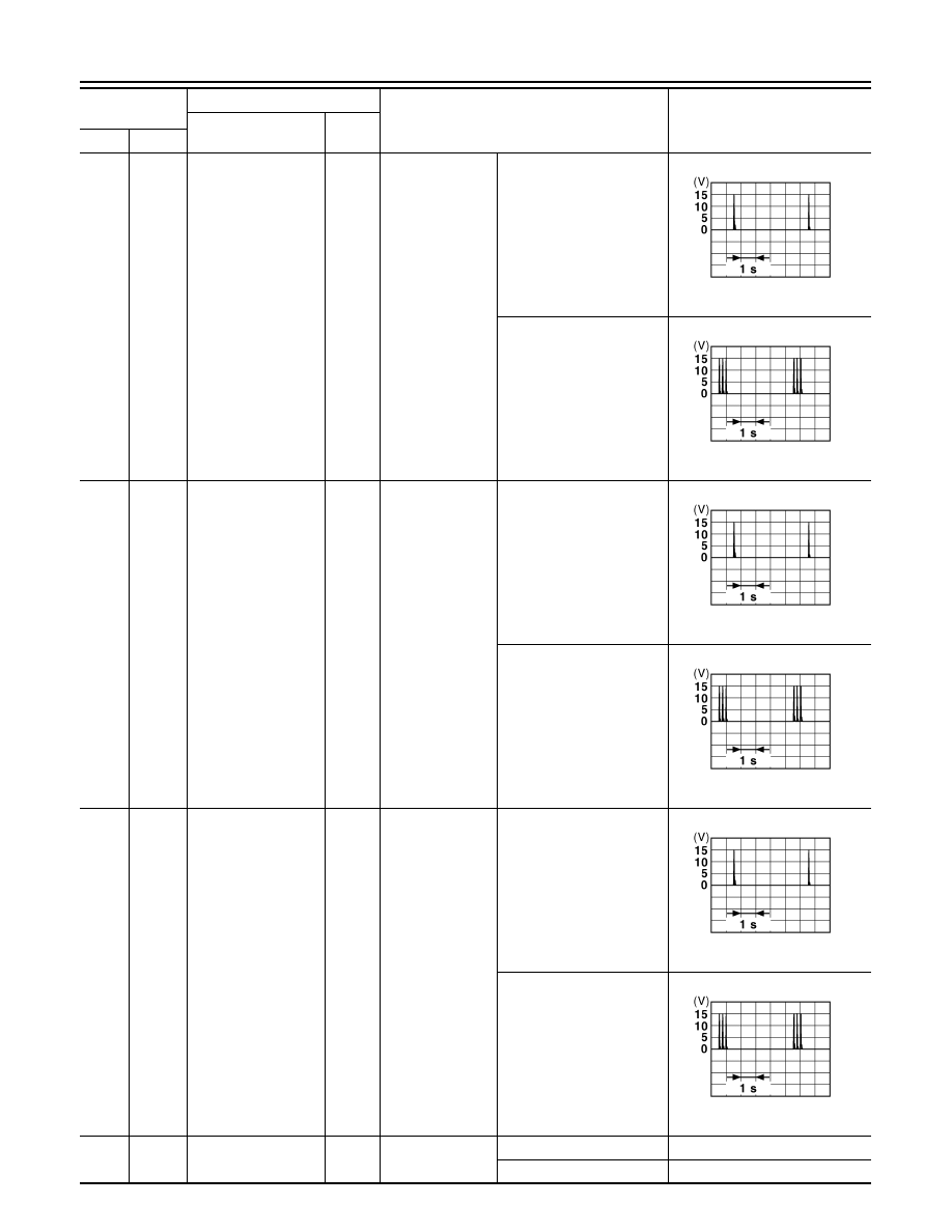
Ground
Luggage room anten-
na (
−
)
Output
Ignition switch
OFF
When Intelligent Key is in
the passenger compart-
ment
When Intelligent Key is not
in the passenger compart-
ment
Terminal No.
(Wire color)
Description
Condition
Value
(Approx.)
Signal name
Input/
Output
+
–
PKID0926E
PKID0926E
PKID0926E
JMKIA0062GB
JMKIA0063GB
PCS-88
< ECU DIAGNOSIS INFORMATION >
[POWER DISTRIBUTION SYSTEM]
BCM (BODY CONTROL MODULE)
35
(V)
Ground
Luggage room anten-
na (+)
Output
Ignition switch
OFF
When Intelligent Key is in
the passenger compart-
ment
When Intelligent Key is not
in the passenger compart-
ment
38
(B)
Ground
Back door antenna (
−
)
Output
When the back
door opener re-
quest switch is
operated with ig-
nition switch OFF
When Intelligent Key is in
the antenna detection area
When Intelligent Key is not
in the antenna detection
area
39
(W)
Ground
Back door antenna
(+)
Output
When the back
door opener re-
quest switch is
operated with ig-
nition switch OFF
When Intelligent Key is in
the antenna detection area
When Intelligent Key is not
in the antenna detection
area
47
(Y)
Ground
Ignition relay (IPDM
E/R) control
Output
Ignition switch
OFF or ACC
12 V
ON
0 V
Terminal No.
(Wire color)
Description
Condition
Value
(Approx.)
Signal name
Input/
Output
+
–
JMKIA0062GB
JMKIA0063GB
JMKIA0062GB
JMKIA0063GB
JMKIA0062GB
JMKIA0063GB
PCS
BCM (BODY CONTROL MODULE)
PCS-89
< ECU DIAGNOSIS INFORMATION >
[POWER DISTRIBUTION SYSTEM]
C
D
E
F
G
H
I
J
K
L
B
A
O
P
N
48
(W)
Ground
Back door opener
switch operation
Output
Back door opener
switch
Not pressed
12 V
Pressed
0 V
52
(LG)
Ground
Starter relay control
Output
Ignition switch
ON
When selector lever is in P
or N position
12 V
When selector lever is not
in P or N position
0 V
61
(W)
Ground
Back door opener re-
quest switch
Input
Back door re-
quest switch
ON (Pressed)
0 V
OFF (Not pressed)
1.0 V
64
(L)
Ground
Intelligent Key warn-
ing buzzer (Engine
room)
Output
Intelligent Key
warning buzzer
(Engine room)
Sounding
0 V
Not sounding
12 V
65
(O)
Ground
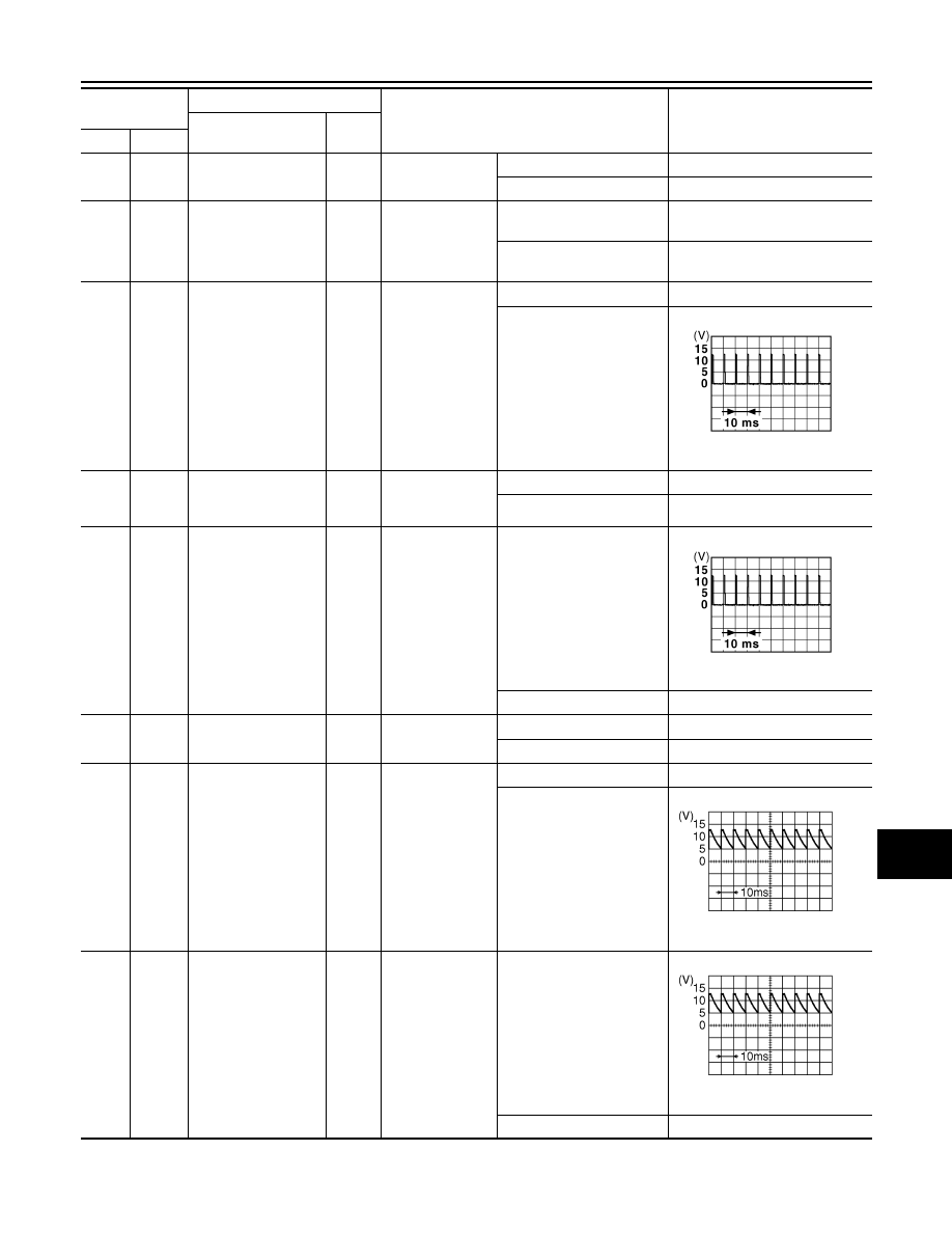
Rear wiper stop posi-
tion
Input
Rear wiper
In stop position
1.0 V
Not in stop position
0 V
66
(LG)
Ground
Back door switch
Input
Back door switch
OFF (Door close)
12 V
ON (Door open)
0 V
67
(P)
Ground
Back door opener
switch
Input
Back door opener
switch
Pressed
0 V
Not pressed
8.5 - 9.0 V
68
(BR)
Ground
Rear RH door switch
Input
Rear RH door
switch
OFF (Door close)
8.5 - 9.0 V
ON (Door open)
0 V
Terminal No.
(Wire color)
Description
Condition
Value
(Approx.)
Signal name
Input/
Output
+
–
JPMIA0016GB
JPMIA0016GB
JPMIA0594GB
JPMIA0594GB
Нет комментариевНе стесняйтесь поделиться с нами вашим ценным мнением.
Текст