Infiniti FX35, FX50 (S51). Manual — part 1426

PCS-62
< DTC/CIRCUIT DIAGNOSIS >
[POWER DISTRIBUTION SYSTEM]
B261A PUSH-BUTTON IGNITION SWITCH
3.
Check continuity between IPDM E/R harness connector and ground.
Is the inspection result normal?
YES
>> GO TO 6.
NO
>> Repair or replace harness.
4.
CHECK IGNITION SWITCH OUTPUT SIGNAL (BCM)
1.
Connect BCM connector.
2.
Check voltage between BCM harness connector and ground.
Is the inspection result normal?
YES
>> GO TO 5.
NO
>> Replace BCM. Refer to
BCS-83, "Removal and Installation"
5.
CHECK PUSH-BUTTON IGNITION SWITCH CIRCUIT (BCM)
1.
Disconnect BCM connector and IPDM E/R connector.
2.
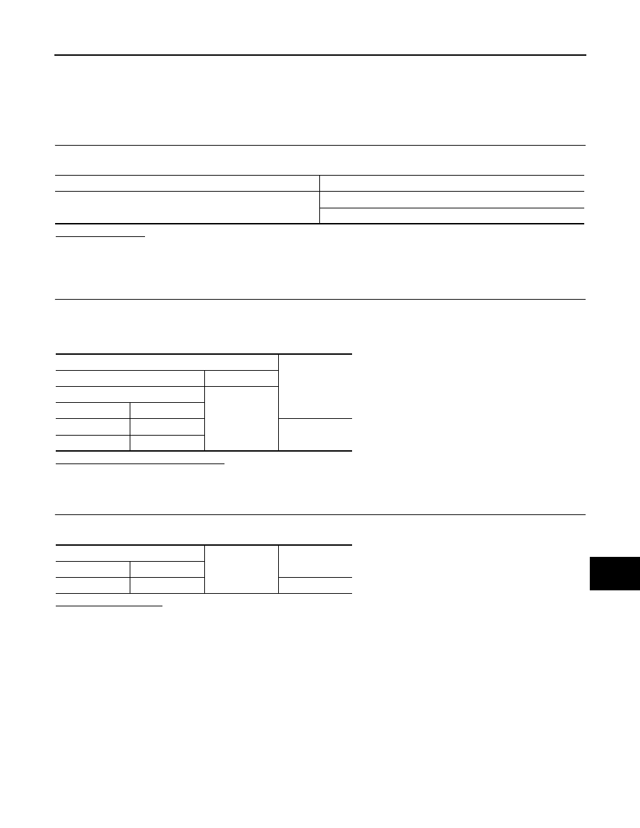
Check continuity between BCM harness connector and push-button ignition switch harness connector.
3.
Check continuity between BCM harness connector and ground.
Is the inspection result normal?
YES
>> GO TO 6.
NO
>> Repair or replace harness.
6.
CHECK INTERMITTENT INCIDENT
GI-36, "Intermittent Incident"
>> INSPECTION END
IPDM E/R
Push-button ignition switch
Continuity
Connector
Terminal
Connector
Terminal
E5
28
M50
4
Existed
IPDM E/R
Ground
Continuity
Connector
Terminal
E5
28
Not existed
(+)
(–)
Voltage (V)
(Approx.)
BCM
Connector
Terminal
M122
89
Ground
Battery voltage
BCM
Push-button ignition switch
Continuity
Connector
Terminal
Connector
Terminal
M122
89
M50
4
Existed
BCM
Ground
Continuity
Connector
Terminal
M122
89
Not existed
PCS
POWER SUPPLY AND GROUND CIRCUIT
PCS-63
< DTC/CIRCUIT DIAGNOSIS >
[POWER DISTRIBUTION SYSTEM]
C
D
E
F
G
H
I
J
K
L
B
A
O
P
N
POWER SUPPLY AND GROUND CIRCUIT
BCM
BCM : Diagnosis Procedure
INFOID:0000000005589415
1.
CHECK FUSE AND FUSIBLE LINK
Check that the following fuse and fusible link are not blown.
Is the fuse fusing?
YES
>> Replace the blown fuse or fusible link after repairing the affected circuit if a fuse or fusible link is
blown.
NO
>> GO TO 2.
2.
CHECK POWER SUPPLY CIRCUIT
1.
Turn ignition switch OFF.
2.
Disconnect BCM connectors.
3.
Check voltage between BCM harness connector and ground.
Is the measurement value normal?
YES
>> GO TO 3.
NO
>> Repair harness or connector.
3.
CHECK GROUND CIRCUIT
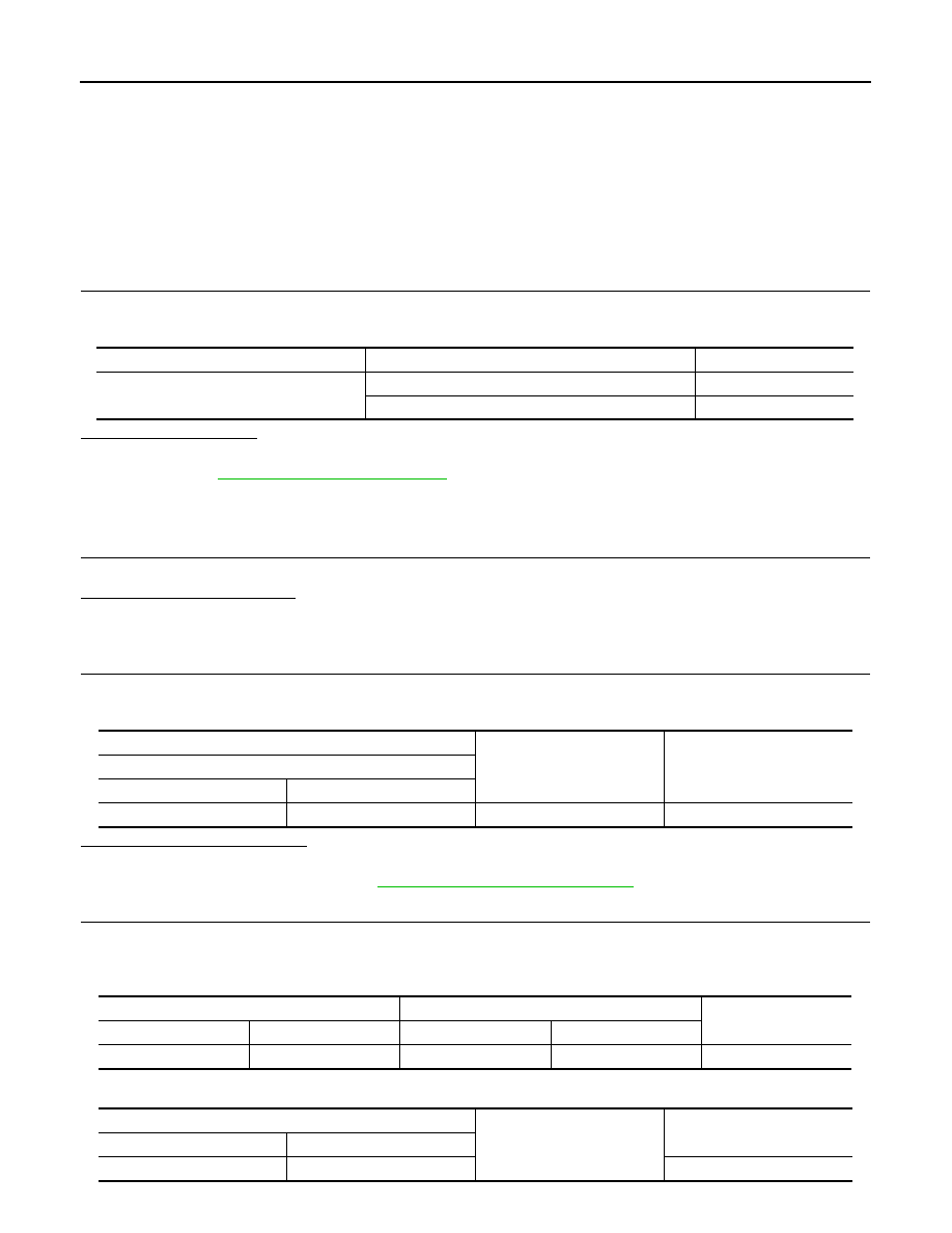
Check continuity between BCM harness connector and ground.
Does continuity exist?
YES
>> INSPECTION END
NO
>> Repair harness or connector.
Signal name
Fuse and fusible link No.
Battery power supply
L
10
Terminals
Voltage
(Approx.)
(+)
(
−
)
BCM
Ground
Connector
Terminal
M118
1
Battery voltage
M119
11
BCM
Ground
Continuity
Connector
Terminal
M119
13
Existed
PCS-64
< DTC/CIRCUIT DIAGNOSIS >
[POWER DISTRIBUTION SYSTEM]
PUSH-BUTTON IGNITION SWITCH
PUSH-BUTTON IGNITION SWITCH
Description
INFOID:0000000005240697
BCM transmits the change in the power supply position with the push-button ignition switch to IPDM E/R via
the CAN communication line. IPDM E/R transmits the power supply position status via CAN communication
line to BCM.
Component Function Check
INFOID:0000000005240698
1.
CHECK FUNCTION
1.
Select “PUSH SW” in “Data Monitor” mode with CONSULT-III.
2.
Check the push-button ignition switch signal under the following condition.
Is the indication normal?
YES
>> INSPECTION END
NO
>> Go to
.
Diagnosis Procedure
INFOID:0000000005240699
1.
CHECK PUSH-BUTTON IGNITION SWITCH OPERATION
Press push-button ignition switch and check if it turns ON.
Does ignition switch turn ON?
YES
>> GO TO 2.
NO
>> GO TO 4.
2.
CHECK IGNITION SWITCH OUTPUT SIGNAL (IPDM E/R)
1.
Disconnect push-button ignition switch connector and BCM connector.
2.
Check voltage between IPDM E/R harness connector and ground.
Is the inspection result normal?
YES
>> GO TO 3.
NO
>> Replace IPDM E/R. Refer to
PCS-34, "Removal and Installation"
3.
CHECK PUSH-BUTTON IGNITION SWITCH CIRCUIT (IPDM E/R)
1.
Disconnect IPDM E/R connector.
2.
Check continuity between IPDM E/R harness connector and push-button ignition switch harness connec-
tor.
3.
Check continuity between IPDM E/R harness connector and ground.
Test item
Condition
Status
PUSH SW
Push-button ignition switch is pressed
ON
Push-button ignition switch is not pressed
OFF
(+)
(–)
Voltage (V)
(Approx.)
IPDM E/R
Connector
Terminal
E5
28
Ground
Battery voltage
IPDM E/R
Push-button ignition switch
Continuity
Connector
Terminal
Connector
Terminal
E5
28
M50
4
Existed
IPDM E/R
Ground
Continuity
Connector
Terminal
E5
28
Not existed

PCS
PUSH-BUTTON IGNITION SWITCH
PCS-65
< DTC/CIRCUIT DIAGNOSIS >
[POWER DISTRIBUTION SYSTEM]
C
D
E
F
G
H
I
J
K
L
B
A
O
P
N
Is the inspection result normal?
YES
>> GO TO 6.
NO
>> Repair or replace harness.
4.
CHECK IGNITION SWITCH OUTPUT SIGNAL (BCM)
1.
Disconnect push-button ignition switch connector and IPDM E/R connector.
2.
Check voltage between BCM harness connector and ground.
Is the inspection result normal?
YES
>> GO TO 5.
NO
>> Replace BCM. Refer to
BCS-83, "Removal and Installation"
5.
CHECK PUSH-BUTTON IGNITION SWITCH CIRCUIT (BCM)
1.
Disconnect BCM connector.
2.
Check continuity between BCM harness connector and push-button ignition switch harness connector.
3.
Check continuity between BCM harness connector and ground.
Is the inspection result normal?
YES
>> GO TO 6.
NO
>> Repair or replace harness.
6.
CHECK PUSH-BUTTON IGNITION SWITCH
GI-36, "Intermittent Incident"
.
Is the inspection result normal?
YES
>> GO TO 7.
NO
>> Replace push-button ignition switch. Refer to
PCS-133, "Removal and Installation"
.
7.
CHECK PUSH-BUTTON IGNITION SWITCH GROUND CIRCUIT
Check continuity between push-button ignition switch and ground.
Is the inspection result normal?
YES
>> GO TO 8.
NO
>> Repair or replace harness.
8.
CHECK INTERMITTENT INCIDENT
GI-36, "Intermittent Incident"
.
>> INSPECTION END
(+)
(–)
Voltage (V)
(Approx.)
BCM
Connector
Terminal
M122
89
Ground
Battery voltage
BCM
Push-button ignition switch
Continuity
Connector
Terminal
Connector
Terminal
M122
89
M50
4
Existed
BCM
Ground
Continuity
Connector
Terminal
M122
89
Not existed
Push-button ignition switch
Ground
Continuity
Connector
Terminal
M50
1
Existed
Нет комментариевНе стесняйтесь поделиться с нами вашим ценным мнением.
Текст