Infiniti FX35, FX50 (S51). Manual — part 761
INSPECTION AND ADJUSTMENT
EC-585
< BASIC INSPECTION >
[VK50VE]
C
D
E
F
G
H
I
J
K
L
M
A
EC
N
P
O
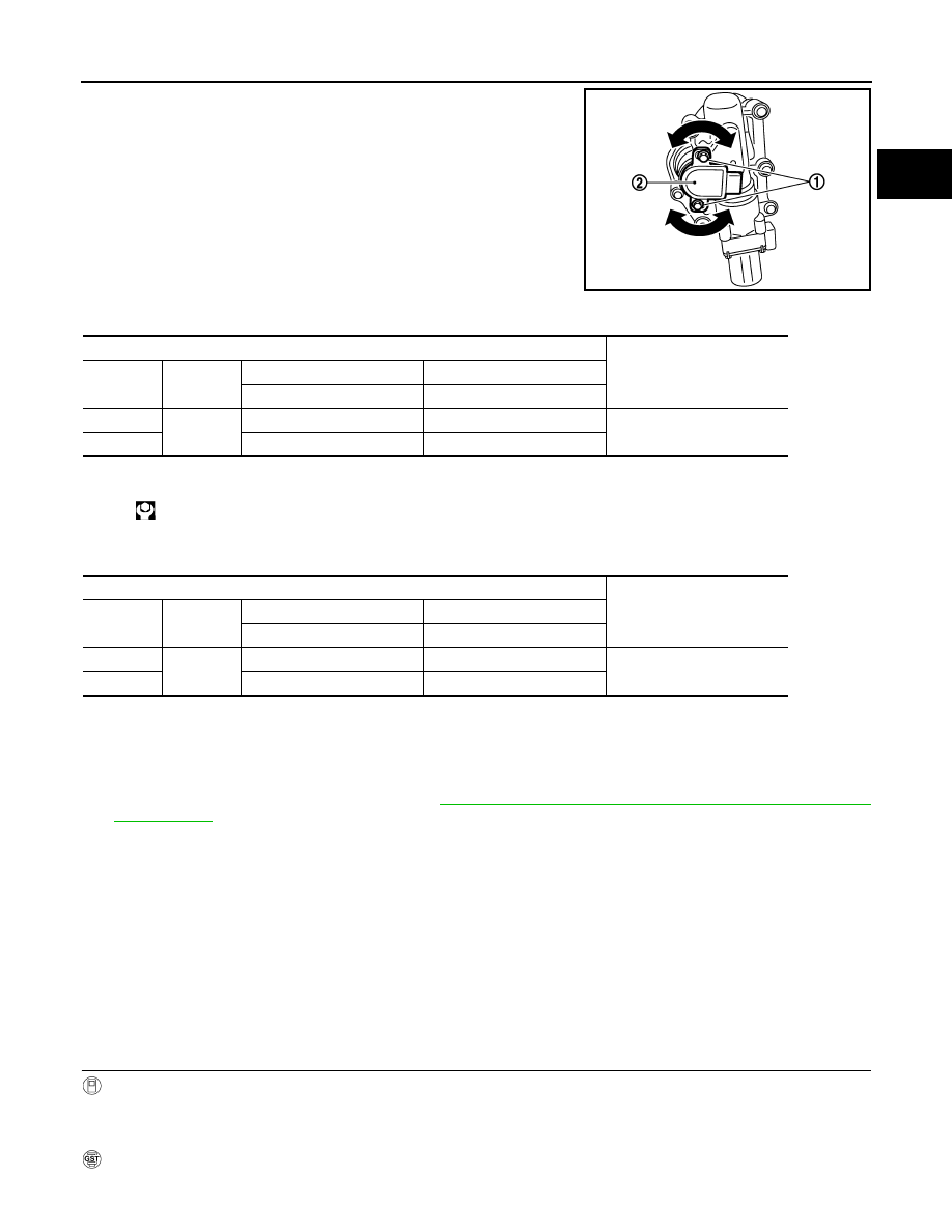
7.
Loosen the VVEL control shaft position sensor mounting bolts
(1).
8.
Turn the VVEL control shaft position sensor (2) clockwise and
counterclockwise while monitoring the output voltage between
the VVEL control module terminals with a tester and adjust the
output voltage to be within the standard value.
9.
Tighten the VVEL control shaft position sensor mounting bolts.
10. Reconfirm that the output voltage of VVEL control shaft position sensor is within the standard value.
NOTE:
If it varies from the standard value after the mounting bolts are tightened, perform steps 7 to 9 again.
11. Turn ignition switch OFF and wait at least 10 seconds.
12. Start engine and warm it up to normal operating temperature.
13. Turn ignition switch OFF and wait at least 10 seconds.
14. Perform Idle Air Volume Learning. Refer to
EC-582, "IDLE AIR VOLUME LEARNING : Special Repair
.
>> INSPECTION END
MIXTURE RATIO SELF-LEARNING VALUE CLEAR
MIXTURE RATIO SELF-LEARNING VALUE CLEAR : Description
INFOID:0000000005237166
This describes how to erase the mixture ratio self-learning value. For the actual procedure, follow the instruc-
tions in “Diagnosis Procedure”.
MIXTURE RATIO SELF-LEARNING VALUE CLEAR : Special Repair Requirement
INFOID:0000000005237167
1.
START
With CONSULT-III
1.
Start engine and warm it up to normal operating temperature.
2.
Select “SELF-LEARNING CONT” in “WORK SUPPORT” mode with CONSULT-III.
3.
Clear mixture ratio self-learning value by touching “CLEAR”.
With GST
1.
Start engine and warm it up to normal operating temperature.
JMBIA1557ZZ
VVEL control module
Voltage
Bank
Connector
+
–
Terminal
Terminal
1
E16
3
6
500
±
48 mV
2
5
4
:
7.0 N•m (0.71 kg-m, 62 in-lb)
VVEL control module
Voltage
Bank
Connector
+
–
Terminal
Terminal
1
E16
3 6
500
±
48 mV
2
5
4
EC-586
< BASIC INSPECTION >
[VK50VE]
INSPECTION AND ADJUSTMENT
2.
Turn ignition switch OFF.
3.
Disconnect mass air flow sensor (bank 1) harness connector.
4.
Restart engine and let it idle for at least 5 seconds.
5.
Stop engine and reconnect mass air flow sensor (bank 1) harness connector.
6.
Select Service $03 with GST. Check DTC P0102 is detected.
7.
Select Service $04 with GST to erase the DTC P0102.
>> END
ENGINE CONTROL SYSTEM
EC-587
< SYSTEM DESCRIPTION >
[VK50VE]
C
D
E
F
G
H
I
J
K
L
M
A
EC
N
P
O
SYSTEM DESCRIPTION
ENGINE CONTROL SYSTEM
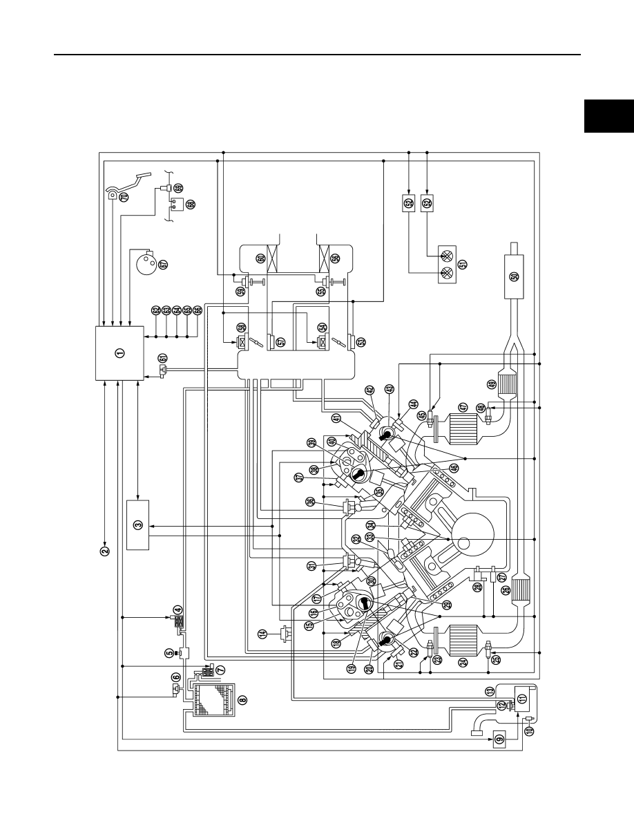
System Diagram
INFOID:0000000005237168
JMBIA1566ZZ
EC-588
< SYSTEM DESCRIPTION >
[VK50VE]
ENGINE CONTROL SYSTEM
System Description
INFOID:0000000005237169
ECM performs various controls such as fuel injection control and ignition timing control.
1.
ECM
2.
CAN communication
3.
VVEL control module
4.
EVAP canister purge volume control
solenoid valve
5.
EVAP service port
6.
EVAP control system pressure sen-
sor
7.
EVAP canister vent control valve
8.
EVAP canister
9.
Fuel pump control module (FPCM)
10. Fuel tank temperature sensor
11.
Fuel level sensor unit and fuel pump 12. Fuel pressure regulator
13. Fuel tank
14. Fuel damper
15. VVEL actuator motor
16. VVEL control shaft position sensor
17. Intake valve timing control solenoid
valve
18. Ignition coil (with power transistor)
19. Camshaft position sensor
20. PCV valve
21. Exhaust valve timing control sole-
noid valve
22. Exhaust valve timing control position
sensor
23. Air fuel ratio (A/F) sensor 1
24. Three way catalyst (manifold)
25. Heated oxygen sensor 2
26. Three way catalyst (under floor)
27. Engine oil temperature sensor
28. Crankshaft position sensor
29. Spark plug
30. Fuel injector
31. Fuel damper
32. Engine coolant temperature sensor
33. Knock sensor
34. Knock sensor
35. Fuel injector
36. Fuel damper
37. Intake valve timing control solenoid
valve
38. VVEL actuator motor
39. Camshaft position sensor
40. VVEL control shaft position sensor
41. Ignition coil (with power transistor)
42. PCV valve
43. Exhaust valve timing control position
sensor
44. Exhaust valve timing control sole-
noid valve
45. Air fuel ratio (A/F) sensor 1
46. Spark plug
47. Three way catalyst (manifold)
48. Heated oxygen sensor 2
49. Three way catalyst (under floor)
50. Muffler
51. Cooling fan motor
52. Cooling fan control module
53. Throttle position sensor
54. Electric throttle control actuator
55. Mass air flow sensor (with intake air
temperature sensor)
56. Air cleaner
57. Throttle position sensor
58. Electric throttle control actuator
59. Mass air flow sensor
60. Air cleaner
61. Manifold Absolute Pressure Sensor
(This sensor is not for controlling the
engine system, nor for the on board
diagnosis.)
62. Park/neutral position (PNP) signal
63. Power steering pressure sensor
64. Refrigerant pressure sensor
65. Snow mode switch
66. Stop lamp switch
67. Ignition switch
68. Battery
69. Battery current sensor
70. Accelerator pedal position sensor
Нет комментариевНе стесняйтесь поделиться с нами вашим ценным мнением.
Текст