Infiniti FX35, FX50 (S51). Manual — part 32

ADP-120
< DTC/CIRCUIT DIAGNOSIS >
DOOR MIRROR MOTOR
DOOR MIRROR MOTOR
Description
INFOID:0000000005249768
It makes mirror face operate from side to side and up and down with the electric power that automatic drive
positioner control unit supplies.
Component Function Check
INFOID:0000000005249769
1.
CHECK DOOR MIRROR MOTOR FUNCTION
Check the operation with “MIRROR MOTOR RH” and “MIRROR MOTOR LH” in “ACTIVE TEST” mode with
CONSULT-III
Refer to
ADP-42, "CONSULT-III Function"
.
Is the inspection result normal?
YES
>> INSPECTION END
NO
>> Perform diagnosis procedure. Refer to
ADP-120, "Diagnosis Procedure"
.
Diagnosis Procedure
INFOID:0000000005249770
1.
CHECK DOOR MIRROR MOTOR INPUT SIGNAL
1.
Turn ignition switch OFF.
2.
Disconnect door mirror connector.
3.
Turn ignition switch ON.
4.
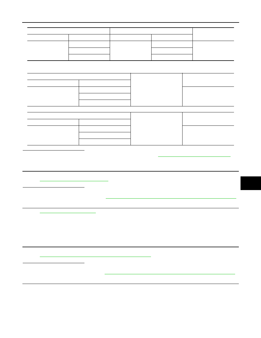
Check voltage between door mirror connector and ground.
Is the inspection result normal?
YES
>> GO TO 3.
NO
>> GO TO 2.
2.
CHECK HARNESS CONTINUITY
1.
Turn ignition switch OFF.
2.
Disconnect automatic drive positioner control unit connector.
3.
Check continuity between automatic drive positioner control unit connector and door mirror connector.
[Door mirror driver side]
(+)
(–)
Condition
Voltage (V)
(Approx.)
Door mirror
Connector
Terminal
D3 (Driver side)
D33 (Passenger
side)
12
Ground
Door mirror remote
control switch
UP
Battery voltage
Other than above
0
11
LEFT
Battery voltage
Other than above
0
10
DOWN / RIGHT
Battery voltage
Other than above
0
Automatic drive positioner control unit
Door mirror (driver side)
Continuity
Connector
Terminal
Connector
Terminal
M51
16
D3
10
Existed
31
12
32
11
DOOR MIRROR MOTOR
ADP-121
< DTC/CIRCUIT DIAGNOSIS >
C
D
E
F
G
H
I
K
L
M
A
B
ADP
N
O
P
[Door mirror passenger side]
4.
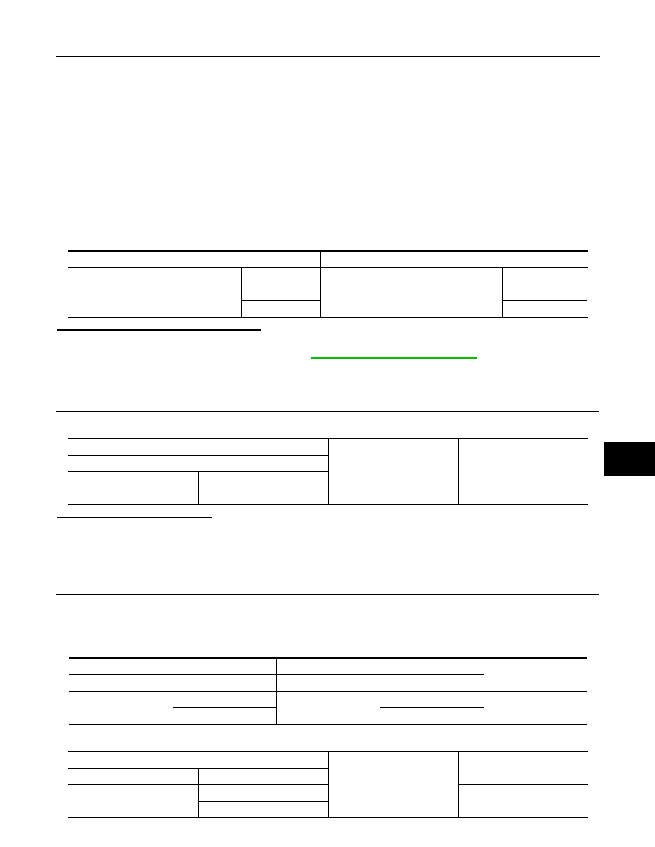
Check continuity between automatic drive positioner control unit connector and ground.
[Door mirror driver side]
[Door mirror passenger side]
Is the inspection result normal?
YES
>> Replace automatic drive positioner control unit. Refer to
ADP-216, "Removal and Installation"
.
NO
>> Repair or replace harness.
3.
CHECK DOOR MIRROR MOTOR
Check door mirror motor.
Refer to
ADP-121, "Component Inspection"
.
Is the inspection result normal?
YES
>> GO TO 4.
NO
>> Replace door mirror. Refer to
MIR-78, "DOOR MIRROR ASSEMBLY : Removal and Installation"
.
4.
CHECK INTERMITTENT INCIDENT
GI-36, "Intermittent Incident"
.
>> INSPECTION END
Component Inspection
INFOID:0000000005249771
1.
CHECK DOOR MIRROR MOTOR-I
Check that door mirror motor does not trap foreign objects and does not have any damage.
Refer to
MIR-78, "DOOR MIRROR ASSEMBLY : Exploded View"
.
Is the inspection result normal?
YES
>> GO TO 2.
NO
>> Replace door mirror.Refer to
MIR-78, "DOOR MIRROR ASSEMBLY : Removal and Installation"
2.
CHECK DOOR MIRROR MOTOR-II
1.
Turn ignition switch OFF.
2.
Disconnect door mirror connector.
3.
Apply 12V to each power supply terminal of door mirror motor.
Automatic drive positioner control unit
Door mirror (passenger side)
Continuity
Connector
Terminal
Connector
Terminal
M51
14
D33
12
Existed
15
11
30
10
Automatic drive positioner control unit
Ground
Continuity
Connector
Terminal
M51
16
Not existed
31
32
Automatic drive positioner control unit
Ground
Continuity
Connector
Terminal
M51
14
Not existed
15
30

ADP-122
< DTC/CIRCUIT DIAGNOSIS >
DOOR MIRROR MOTOR
Is the inspection result normal?
YES
>> INSPECTION END
NO
>> Replace door mirror. Refer to
MIR-78, "DOOR MIRROR ASSEMBLY : Removal and Installation"
.
Door mirror
Operational direction
Connector
Terminal
(+)
(–)
D3 (Driver side)
D33 (Passenger side)
10
11
RIGHT
11
10
LEFT
12
10
UP
10
12
DOWN
SEAT MEMORY INDICATOR
ADP-123
< DTC/CIRCUIT DIAGNOSIS >
C
D
E
F
G
H
I
K
L
M
A
B
ADP
N
O
P
SEAT MEMORY INDICATOR
Description
INFOID:0000000005249772
• Memory switch is equipped on the seat memory switch installed to the driver side door trim. The operation
signal is inputted to the automatic drive positioner control unit when the memory switch is operated.
• The status of automatic drive positioner system can be checked according to the illuminating/flashing status.
Component Function Check
INFOID:0000000005249773
1.
CHECK FUNCTION
1.
Turn ignition switch ON.
2.
Select “MEMORY SW INDCTR” in “Active test” mode with CONSULT-III.
3.
Check the memory indicator operation.
Is the operation of relevant parts normal?
YES
>> INSPECTION END
NO
>> Perform diagnosis procedure. Refer to
ADP-123, "Diagnosis Procedure"
Diagnosis Procedure
INFOID:0000000005249774
1.
CHECK MEMORY INDICATOR POWER SUPPLY
Check voltage between seat memory switch harness connector and ground.
Is the inspection result normal?
YES
>> GO TO 2.
NO
>>
Check the following.
• 10A fuse [No.10 located in fuse block (J/B)].
• Harness for open or short between memory indicator and fuse.
2.
CHECK MEMORY INDICATOR CIRCUIT
1.
Turn ignition switch OFF.
2.
Disconnect automatic drive positioner control unit and seat memory switch connector.
3.
Check continuity between automatic drive positioner control unit harness connector and seat memory
switch harness connector.
4.
Check continuity between automatic drive positioner control unit harness connector and ground.
Test item
Description
MEMORY SW INDCTR
OFF
Memory switch indicator
OFF
ON-1
Indicator 1: ON
ON-2
Indicator 2: ON
(+)
(–)
Voltage (V)
(Approx.)
Seat memory switch
Connector
Terminal
D5
5
Ground
Battery voltage
Automatic drive positioner control unit
Seat memory switch
Continuity
Connector
Terminal
Connector
Terminal
M51
12
D5
6
Existed
13
7
Automatic drive positioner control unit
Ground
Continuity
Connector
Terminal
M51
12
Not existed
13
Нет комментариевНе стесняйтесь поделиться с нами вашим ценным мнением.
Текст