Infiniti FX35, FX50 (S51). Manual — part 200

AV
BOSE AMP.
AV-573
< REMOVAL AND INSTALLATION >
[NAVIGATION (TWIN MONITOR)]
C
D
E
F
G
H
I
J
K
L
M
B
A
O
P
BOSE AMP.
Exploded View
INFOID:0000000005247420
REMOVAL
DISASSEMBLY
Removal and Installation
INFOID:0000000005247421
REMOVAL
1.
Remove luggage floor spacer (LH). Refer to
.
2.
Remove BOSE amp. mounting nuts.
3.
Disconnect connector and remove BOSE amp.
INSTALLATION
Installation is the reverse order of removal.
JSNIA1462ZZ
1.
BOSE amp.
JSNIA1539ZZ
1.
BOSE amp.
2.
Bracket

AV-574
< REMOVAL AND INSTALLATION >
[NAVIGATION (TWIN MONITOR)]
ANTENNA BASE
ANTENNA BASE
Exploded View
INFOID:0000000005247422
Removal and Installation
INFOID:0000000005247423
REMOVAL
1.
Remove headlining (rear). Keep a service area. Refer to
.
2.
Remove antenna base mounting nut.
3.
Disconnect connector and remove antenna base.
INSTALLATION
Installation is the reverse order of removal.
CAUTION:
Be careful about tightening torque. Antenna sensitivity becomes poor, and when it is excessive, roof
panel may be deformed, when antenna base mounting nut tightening torque is loose.
JSNIA1463ZZ
1.
Antenna rod
2.
Antenna base
for symbols in the figure.

AV
MULTIFUNCTION SWITCH
AV-575
< REMOVAL AND INSTALLATION >
[NAVIGATION (TWIN MONITOR)]
C
D
E
F
G
H
I
J
K
L
M
B
A
O
P
MULTIFUNCTION SWITCH
Exploded View
INFOID:0000000005247424
REMOVAL
.
DISASSEMBLY
Removal and Installation
INFOID:0000000005247425
REMOVAL
1.
Remove cluster lid D. Refer to
.
2.
Remove multifunction switch mounting screws.
3.
Disconnect connector and remove multifunction switch.
INSTALLATION
Installation is the reverse order of removal.
JSNIA1464ZZ
1.
Cluster lid D
2.
Multifunction switch
AV-576
< REMOVAL AND INSTALLATION >
[NAVIGATION (TWIN MONITOR)]
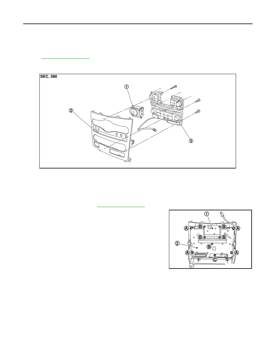
PRESET SWITCH
PRESET SWITCH
Exploded View
INFOID:0000000005247426
REMOVAL
.
DISASSEMBLY
Removal and Installation
INFOID:0000000005247427
REMOVAL
1.
Remove cluster lid C. Refer to
2.
Remove preset switch mounting screws (A), (B) and (C).
3.
Disconnect connector and remove preset switch (2).
INSTALLATION
Installation is the reverse order of removal.
NOTE:
When installing preset switch, do not allow the print wire that connects preset switch and multifunction switch
to get caught in between AV control unit and preset switch.
1.
Clock
2.
Cluster lid C
3.
Preset switch
JPNIA1102ZZ
1.
Clock
JSNIA1481ZZ
Нет комментариевНе стесняйтесь поделиться с нами вашим ценным мнением.
Текст