Infiniti FX35, FX50 (S51). Manual — part 144
AV
GPS ANTENNA
AV-349
< REMOVAL AND INSTALLATION >
[NAVIGATION (SINGLE MONITOR)]
C
D
E
F
G
H
I
J
K
L
M
B
A
O
P
GPS ANTENNA
Exploded View
INFOID:0000000005475597
Removal and Installation
INFOID:0000000005475598
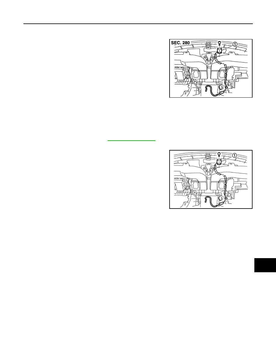
REMOVAL
1.
Remove instrument panel. Refer to
.
2.
Remove GPS antenna mounting screw.
3.
Remove GPS antenna (1).
INSTALLATION
Installation is the reverse order of removal.
JSNIA1610ZZ
1.
GPS antenna
JSNIA1482ZZ
AV-350
< REMOVAL AND INSTALLATION >
[NAVIGATION (SINGLE MONITOR)]
GPS ANTENNA
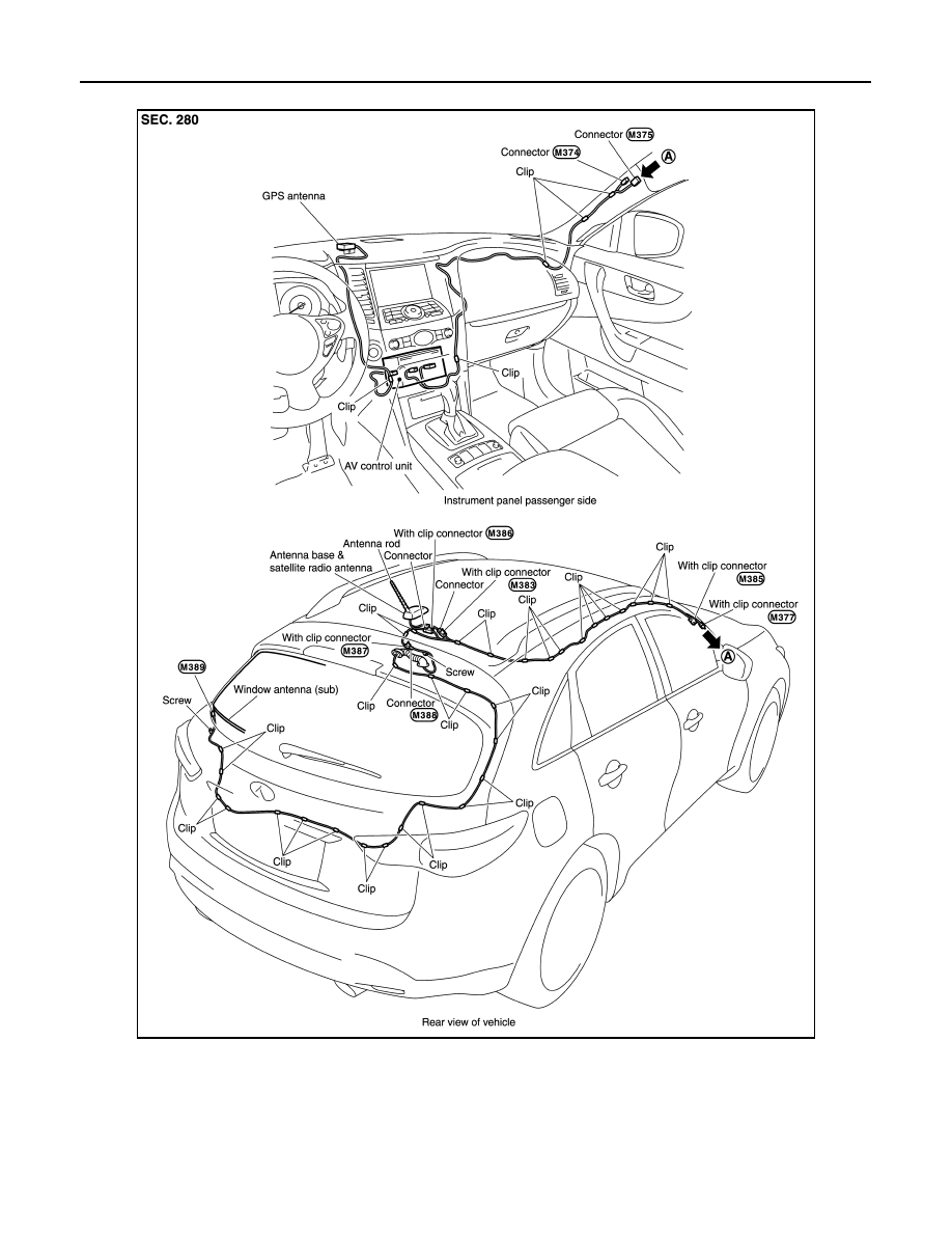
Feeder Layout
INFOID:0000000005475599
JSNIA1468GB
AV
AROUND VIEW MONITOR CONTROL UNIT
AV-351
< REMOVAL AND INSTALLATION >
[NAVIGATION (SINGLE MONITOR)]
C
D
E
F
G
H
I
J
K
L
M
B
A
O
P
AROUND VIEW MONITOR CONTROL UNIT
Exploded View
INFOID:0000000005475600
Removal and Installation
INFOID:0000000005475601
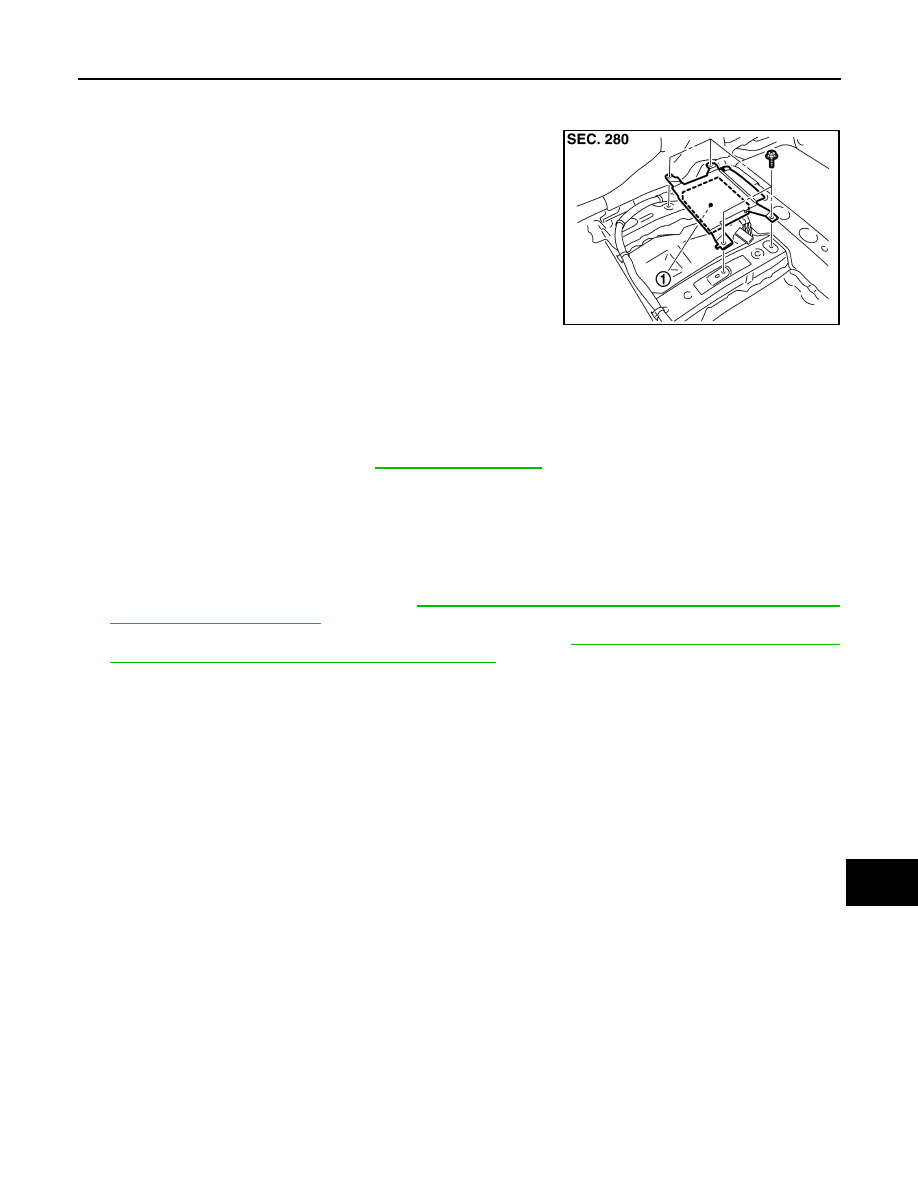
REMOVAL
1.
Remove front seat (LH side). Refer to
.
2.
Remove floor carpet. Keep a service area.
3.
Remove around view monitor control unit mounting screws.
4.
Disconnect connector and remove around view monitor control unit.
INSTALLATION
1.
Installation is the reverse order of removal.
2.
Perform camera image calibration. Refer to
AV-245, "CALIBRATING CAMERA IMAGE (AROUND VIEW
3.
Perform predictive course line center position adjustment. Refer to
AV-245, "PREDICTIVE COURSE LINE
CENTER POSITION ADJUSTMENT : Work Procedure"
CAUTION:
Perform the calibration and perform the writing to the around view monitor control unit when remov-
ing and replacing each camera, removing the camera mounting parts (front grille, door mirror, etc.)
and replacing the around view monitor control unit.
JPNIA0898ZZ
1.
Around view monitor control unit
AV-352
< REMOVAL AND INSTALLATION >
[NAVIGATION (SINGLE MONITOR)]
FRONT CAMERA
FRONT CAMERA
Exploded View
INFOID:0000000005475602
Removal and Installation
INFOID:0000000005475603
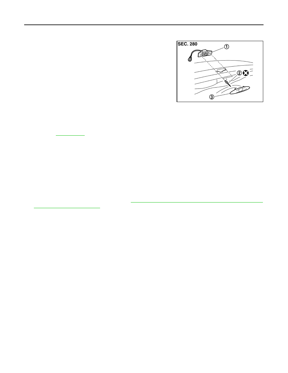
REMOVAL
1.
Remove front camera finisher.
2.
Remove front camera mounting rivet.
3.
Remove front camera.
INSTALLATION
1.
Installation is the reverse order of removal.
2.
Perform camera image calibration. Refer to
AV-245, "CALIBRATING CAMERA IMAGE (AROUND VIEW
CAUTION:
Perform the calibration and perform the writing to the around view monitor control unit when remov-
ing and replacing each camera, removing the camera mounting parts (front grille, door mirror, etc.)
and replacing the around view monitor control unit.
JSNIA1469ZZ
1.
Front camera
2.
Rivet
3.
Front camera finisher
for symbols in the figure.
Нет комментариевНе стесняйтесь поделиться с нами вашим ценным мнением.
Текст