Infiniti FX35, FX50 (S51). Manual — part 80

AV
U1232 STEERING ANGLE SENSOR
AV-93
< DTC/CIRCUIT DIAGNOSIS >
[WITHOUT NAVIGATION]
C
D
E
F
G
H
I
J
K
L
M
B
A
O
P
U1232 STEERING ANGLE SENSOR
DTC Logic
INFOID:0000000005528941
Diagnosis Procedure
INFOID:0000000005528942
1.
ADJUST THE PREDICTIVE COURSE LINE CENTER POSITION OF THE STEERING ANGLE SENSOR
When U1232 is detected, adjust the predictive course line center position of the steering angle sensor.
>> Adjusts the steering angle sensor neutral position on ABS actuator and electrical unit (control unit)
side. Refer to
BRC-9, "ADJUSTMENT OF STEERING ANGLE SENSOR NEUTRAL POSITION :
.
DTC
Display contents of
CONSULT-III
DTC detection condition
Possible malfunction factor
U1232
ST ANGLE SEN CALIB
[1232]
Predictive course line center position adjustment of the
steering angle sensor is incomplete.
Adjust the predictive course line cen-
ter position of the steering angle sen-
sor.
AV-94
< DTC/CIRCUIT DIAGNOSIS >
[WITHOUT NAVIGATION]
U1243 FRONT DISPLAY UNIT
U1243 FRONT DISPLAY UNIT
DTC Logic
INFOID:0000000005528943
Diagnosis Procedure
INFOID:0000000005528944
1.
CHECK FRONT DISPLAY UNIT POWER SUPPLY AND GROUND CIRCUITS
Check front display unit power supply and ground circuits. Refer to
AV-101, "FRONT DISPLAY UNIT : Diagno-
Is inspection result normal?
YES
>> GO TO 2.
NO
>> Repair malfunctioning parts.
2.
CHECK CONTINUITY COMMUNICATION CIRCUITS
1.
Turn ignition switch OFF.
2.
Disconnect front display unit connector and AV control unit connector.
3.
Check continuity between front display unit harness connector and AV control unit harness connector.
4.
Check continuity between front display unit harness connector and ground.
Is inspection result normal?
YES
>> GO TO 3.
NO
>> Repair harness or connector.
3.
CHECK COMMUNICATION SIGNAL
1.
Connect front display unit connector and AV control unit connector.
2.
Turn ignition switch ON.
3.
Check signal between front display unit harness connector and ground.
DTC
Display contents of
CONSULT-III
DTC Detection Condition
Possible causes
U1243
FRONT DISP CONN
[U1243]
When either one of the following items is detected.
• front display unit power supply and ground circuit mal-
function is detected.
• malfunction is detected in communication circuits be-
tween front display unit and AV control unit.
• Front display unit power supply and
ground circuit.
• Communication circuits between
front display unit and AV control
unit.
Front display unit
AV control unit
Continuity
Connector
Terminals
Connector
Terminals
M194
11
M202
70
Existed
22
71
Front display unit
Ground
Continuity
Connector
Terminals
M194
11
Not existed
12
AV
U1243 FRONT DISPLAY UNIT
AV-95
< DTC/CIRCUIT DIAGNOSIS >
[WITHOUT NAVIGATION]
C
D
E
F
G
H
I
J
K
L
M
B
A
O
P
Is inspection result normal?
YES
>> GO TO 4.
NO
>> Replace AV control unit.
4.
CHECK COMMUNICATION SIGNAL
Check signal between front display unit harness connector and ground.
Is inspection result normal?
YES
>> INSPECTION END
NO
>> Replace front display unit.
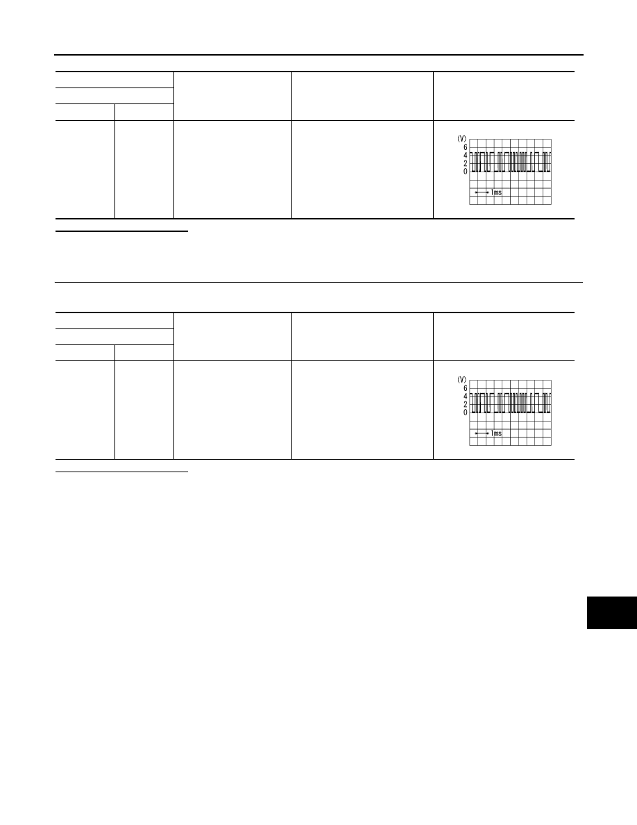
(+)
(
−
)
Condition
Reference value
Front display unit
Connector
Terminal
M194
11
Ground
When adjusting display bright-
ness.
PKIB5039J
(+)
(
−
)
Condition
Reference value
Front display unit
Connector
Terminal
M194
22
Ground
When adjusting display bright-
ness.
PKIB5039J
AV-96
< DTC/CIRCUIT DIAGNOSIS >
[WITHOUT NAVIGATION]
U1255 SATELLITE RADIO TUNER
U1255 SATELLITE RADIO TUNER
DTC Logic
INFOID:0000000005528974
Diagnosis Procedure
INFOID:0000000005528975
1.
CHECK SATELLITE RADIO TUNER POWER SUPPLY AND GROUND CIRCUIT
Check satellite radio tuner power supply and ground circuit. Refer to
AV-103, "SATELLITE RADIO TUNER :
Is the inspection result normal?
YES
>> GO TO 2.
NO
>> Repair malfunctioning parts.
2.
CHECK CONTINUITY COMMUNICATION CIRCUIT AND REQUEST SIGNAL CIRCUIT
1.
Turn ignition switch OFF.
2.
Disconnect AV control unit connector and satellite radio tuner connector.
3.
Check continuity between AV control unit harness connector and satellite radio tuner harness connector.
4.
Check continuity between AV control unit harness connector and ground.
Is the inspection result normal?
YES
>> GO TO 3.
NO
>> Repair harness or connector.
3.
CHECK AV CONTROL UNIT VOLTAGE
1.
Connect AV control unit connector.
2.
Turn ignition switch ON.
3.
Check voltage between AV control unit harness connector and ground.
DTC
Display contents of
CONSULT-III
DTC Detection Condition
Possible causes
U1255
SAT CONN
[U1255]
When either one of the following items is detected:
• satellite radio tuner power supply and ground circuits
malfunction is detected.
• malfunction is detected in communication circuits be-
tween AV control unit and satellite radio tuner.
• malfunction is detected in request signal circuit be-
tween AV control unit and satellite radio tuner.
• Satellite radio tuner power supply
and ground circuits.
• Communication circuits between
AV control unit and satellite radio
tuner.
• Request signal circuit between AV
control unit and satellite radio tun-
er.
AV control unit
Satellite radio tuner
Continuity
Connector
Terminals
Connector
Terminals
M206
129
B236
8
Existed
130
9
122
10
AV control unit
Ground
Continuity
Connector
Terminals
M206
129
Not existed
130
122
(+)
(
−
)
Voltage
(Approx.)
AV control unit
Connector
Terminals
Нет комментариевНе стесняйтесь поделиться с нами вашим ценным мнением.
Текст