Infiniti FX35, FX50 (S51). Manual — part 1712

SRS AIR BAG SYSTEM
SRC-13
< SYSTEM DESCRIPTION >
C
D
E
F
G
I
J
K
L
M
A
B
SRC
N
O
P
Component
Function
Air bag diagnosis sensor unit
Detects a collision and supplies power supply for deployment to air bag module and
pre-tensioner seat belt.
Air bag module
• Driver
• Passenger
• Front side
• Side curtain
Receives signal from air bag diagnosis sensor unit and deploys air bag.
Front seat belt pre-tensioner
Receives signal from air bag diagnosis sensor unit and deploys pre-tensioner seat
belt.
Seat belt buckle switch
Controls deployment timing depending on the seat belt condition that is fastened or
unfastened.
Crash zone sensor
Transmits signal to air bag diagnosis sensor unit when a frontal collision occurs.
Satellite sensor (LH/RH)
Transmits signal to air bag diagnosis sensor unit when a side collision occurs.
Occupant Detection System
Detects front passenger seat occupant and judges whether or not deploys front pas-
senger seat air bag.
Combination meter (air bag warning lamp)
Indicates air bag malfunctioning and deployment by blinking and illuminating air bag
warning lamp.
Front passenger air bag OFF indicator
Indicates whether or not front passenger air bag is in activation mode subject to the
judgement by occupant detection system.
Combination switch (spiral cable)
Supplies power supply to driver air bag module on steering wheel.
SRC-14
< SYSTEM DESCRIPTION >
OCCUPANT DETECTION SYSTEM
OCCUPANT DETECTION SYSTEM
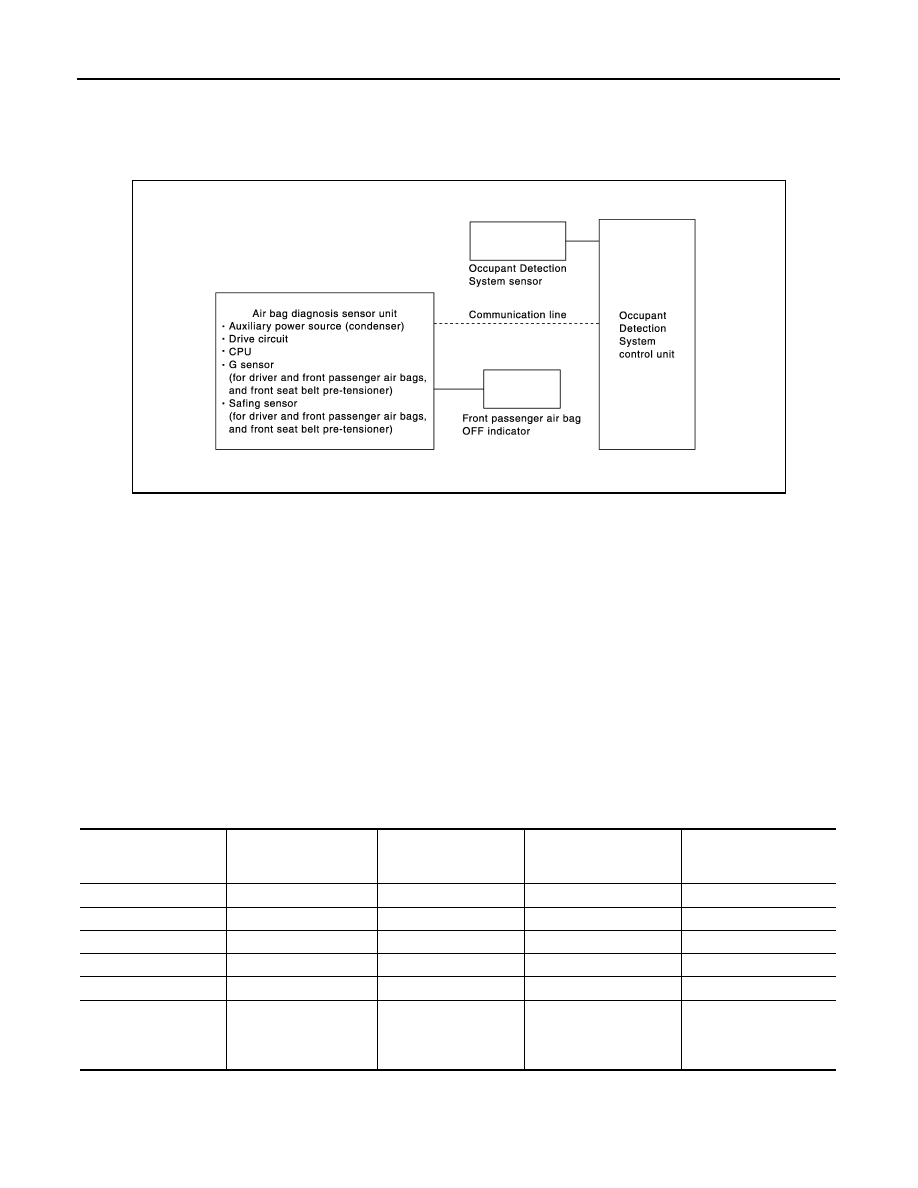
System Diagram
INFOID:0000000005241053
OCCUPANT DETECTION SYSTEM
System Description
INFOID:0000000005241054
This Occupant Detection System has the following functions.
1.
Suppress the deployment of front passenger air bag when front passenger seat is empty, or when occu-
pied by child and child-seat. Turns ON front passenger air bag OFF indicator when front passenger seat is
occupied by child-seat and child.
2.
Indicates malfunction portion with blinking times of air bag warning lamp in diagnosis mode.
3.
Indicates the malfunctioning record by CONSULT-III.
4.
When “zero point reset” for occupant detection system is incomplete, CONSULT-III indicates that “zero
point reset” is incomplete.
This function is applied to NISSAN genuine parts only.
NOTE:
• Operation of air bag diagnosis sensor unit when air bag diagnosis sensor unit receives information from
Occupant Detection System.
• Even if zero point reset is “complete”, always perform zero point reset after the removal and installation of
seat or the removal of control unit harness connector.
JMHIA0683GB
Status (front passenger
seat)
Passenger air bag
Front passenger air
bag OFF indicator
Air bag warning lamp
Seat belt warning lamp
(when front passenger
seat is unbuckled)
Empty
Suppress
OFF
OFF
OFF
An object
Suppress
ON
OFF
OFF
Child/ child-seat
Suppress
ON
OFF
ON
Adult
Enable to deploy
OFF
OFF
ON
Malfunction
Suppress
ON
Blinking
OFF
Zero point reset
Not yet performed (NIS-
SAN genuine parts
only)
Suppress
ON
OFF
OFF
OCCUPANT DETECTION SYSTEM
SRC-15
< SYSTEM DESCRIPTION >
C
D
E
F
G
I
J
K
L
M
A
B
SRC
N
O
P
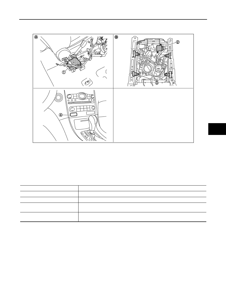
Component Parts Location
INFOID:0000000005241055
Component Description
INFOID:0000000005241056
1.
Air bag diagnosis sensor unit
2.
Occupant Detection System control
unit
3.
Occupant Detection System sensor
4.
Passenger air bag OFF indicator
A.
View with center console assembly
removed
B.
Backside of the seat cushion
JMHIA0688ZZ
Component parts
Outline of function
Occupant Detection System sensor
Detects if the passenger seat is empty or occupied
Occupant Detection System control unit
Transmits the passenger seat status (occupied or empty) to air bag diagnosis sensor unit
Front passenger air bag OFF indicator
Turns the front passenger air bag OFF indicator lamp ON when the front passenger seat is
occupied by a child or a child-seat
Air bag diagnosis sensor unit
Performs the deploy judgement of passenger air bag based on the information from Occu-
pant Detection System control unit

SRC-16
< SYSTEM DESCRIPTION >
DIAGNOSIS SYSTEM (AIRBAG)
DIAGNOSIS SYSTEM (AIRBAG)
Diagnosis Description
INFOID:0000000005241057
CAUTION:
• Never use electrical test equipment on any circuit related to the SRS unless instructed in this Ser-
vice Manual. SRS wiring harnesses can be identified by yellow and/or orange harnesses or harness
connectors.
• Never repair, splice or modify the SRS wiring harness. If the harness is damaged, replace it with a
new one.
• Keep ground portion clean.
DIAGNOSIS FUNCTION
• The SRS self-diagnosis results can be read by using air bag warning lamp and/or CONSULT-III.
• The user mode is exclusively prepared for the customer (driver). This mode warns the driver of a system
malfunction through the operation of the air bag warning lamp.
• The diagnosis mode allows the technician to locate and inspect the malfunctioning part.
• The mode applications for the air bag warning lamp and CONSULT-III are as per the following.
×
: Application, —: Not application
HOW TO PERFORM TROUBLE DIAGNOSIS FOR QUICK AND ACCURATE REPAIR
A good understanding of the malfunction conditions can make troubleshooting faster and more accurate.
In general, each customer feels differently about a malfunction. It is important to fully understand the symp-
toms or conditions for a customer complaint.
Information from Customer.
• WHAT. . Vehicle model.
• WHEN. . Date, Frequencies.
• WHERE. . Road conditions.
• HOW. . Operating conditions, Symptoms.
Preliminary Check.
Check that the following parts are in good order.
• Battery (Refer to
).
• Fuse (Refer to
• System component-to-harness connections.
Air Bag Warning Lamp Diagnosis
INFOID:0000000005241058
SELF-DIAGNOSIS FUNCTION
• The reading of these results is accomplished by “User mode” and “Diagnosis mode”.
• After a malfunction is repaired, turn ignition switch ON. Diagnosis mode returns to the user mode. At that
time, the self-diagnosis result is cleared.
User mode
Diagnosis mode
Display type
Air bag warning lamp
X
X
ON-OFF operation
CONSULT-III
–
X
Monitoring
Нет комментариевНе стесняйтесь поделиться с нами вашим ценным мнением.
Текст