Infiniti FX35, FX50 (S51). Manual — part 1317

LAN-210
< DTC/CIRCUIT DIAGNOSIS >
[CAN SYSTEM (TYPE 5)]
CAN COMMUNICATION CIRCUIT
Is the measurement value within the specification?
YES
>> GO TO 5.
NO
>> Replace the ECM and/or the IPDM E/R.
5.
CHECK SYMPTOM
Connect all the connectors. Check if the symptoms described in the “Symptom (Results from interview with
customer)” are reproduced.
Inspection result
Reproduced>>GO TO 6.
Non-reproduced>>Start the diagnosis again. Follow the trouble diagnosis procedure when past error is
detected.
6.
CHECK UNIT REPRODUCTION
Perform the reproduction test as per the following procedure for each unit.
1.
Turn the ignition switch OFF.
2.
Disconnect the battery cable from the negative terminal.
3.
Disconnect one of the unit connectors of CAN communication system.
NOTE:
ECM and IPDM E/R have a termination circuit. Check other units first.
4.
Connect the battery cable to the negative terminal. Check if the symptoms described in the “Symptom
(Results from interview with customer)” are reproduced.
NOTE:
Although unit-related error symptoms occur, do not confuse them with other symptoms.
Inspection result
Reproduced>>Connect the connector. Check other units as per the above procedure.
Non-reproduced>>Replace the unit whose connector was disconnected.
LAN
MAIN LINE BETWEEN DLC AND M&A CIRCUIT
LAN-211
< DTC/CIRCUIT DIAGNOSIS >
[CAN SYSTEM (TYPE 6)]
C
D
E
F
G
H
I
J
K
L
B
A
O
P
N
DTC/CIRCUIT DIAGNOSIS
MAIN LINE BETWEEN DLC AND M&A CIRCUIT
Diagnosis Procedure
INFOID:0000000005577071
1.
CHECK HARNESS CONTINUITY (OPEN CIRCUIT)
1.
Turn the ignition switch OFF.
2.
Disconnect the battery cable from the negative terminal.
3.
Disconnect the following harness connectors.
-
ECM
-
Unified meter and A/C amp.
4.
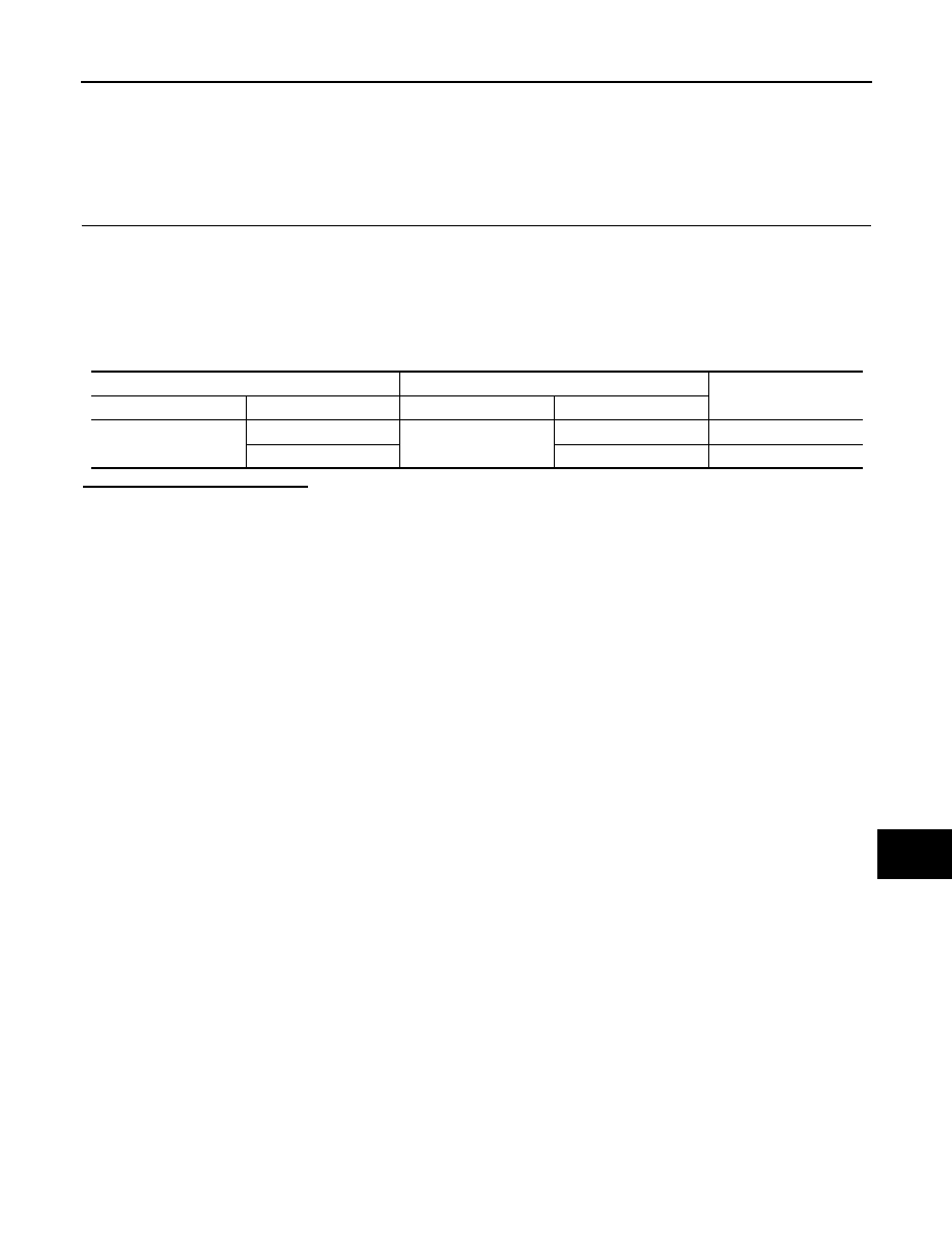
Check the continuity between the data link connector and the unified meter and A/C amp. harness con-
nector.
Is the inspection result normal?
YES (Present error)>>Check CAN system type decision again.
YES (Past error)>>Error was detected in the main line between the data link connector and the unified meter
and A/C amp.
NO
>> Repair the main line between the data link connector and the unified meter and A/C amp.
Data link connector
Unified meter and A/C amp. harness connector
Continuity
Connector No.
Terminal No.
Connector No.
Terminal No.
M24
6
M67
56
Existed
14
72
Existed

LAN-212
< DTC/CIRCUIT DIAGNOSIS >
[CAN SYSTEM (TYPE 6)]
MAIN LINE BETWEEN M&A AND ADP CIRCUIT
MAIN LINE BETWEEN M&A AND ADP CIRCUIT
Diagnosis Procedure
INFOID:0000000005577072
1.
CHECK CONNECTOR
1.
Turn the ignition switch OFF.
2.
Disconnect the battery cable from the negative terminal.
3.
Check the following terminals and connectors for damage, bend and loose connection (connector side
and harness side).
-
Harness connector M7
-
Harness connector B1
Is the inspection result normal?
YES
>> GO TO 2.
NO
>> Repair the terminal and connector.
2.
CHECK HARNESS CONTINUITY (OPEN CIRCUIT)
1.
Disconnect the following harness connectors.
-
Unified meter and A/C amp.
-
Harness connectors M7 and B1
2.
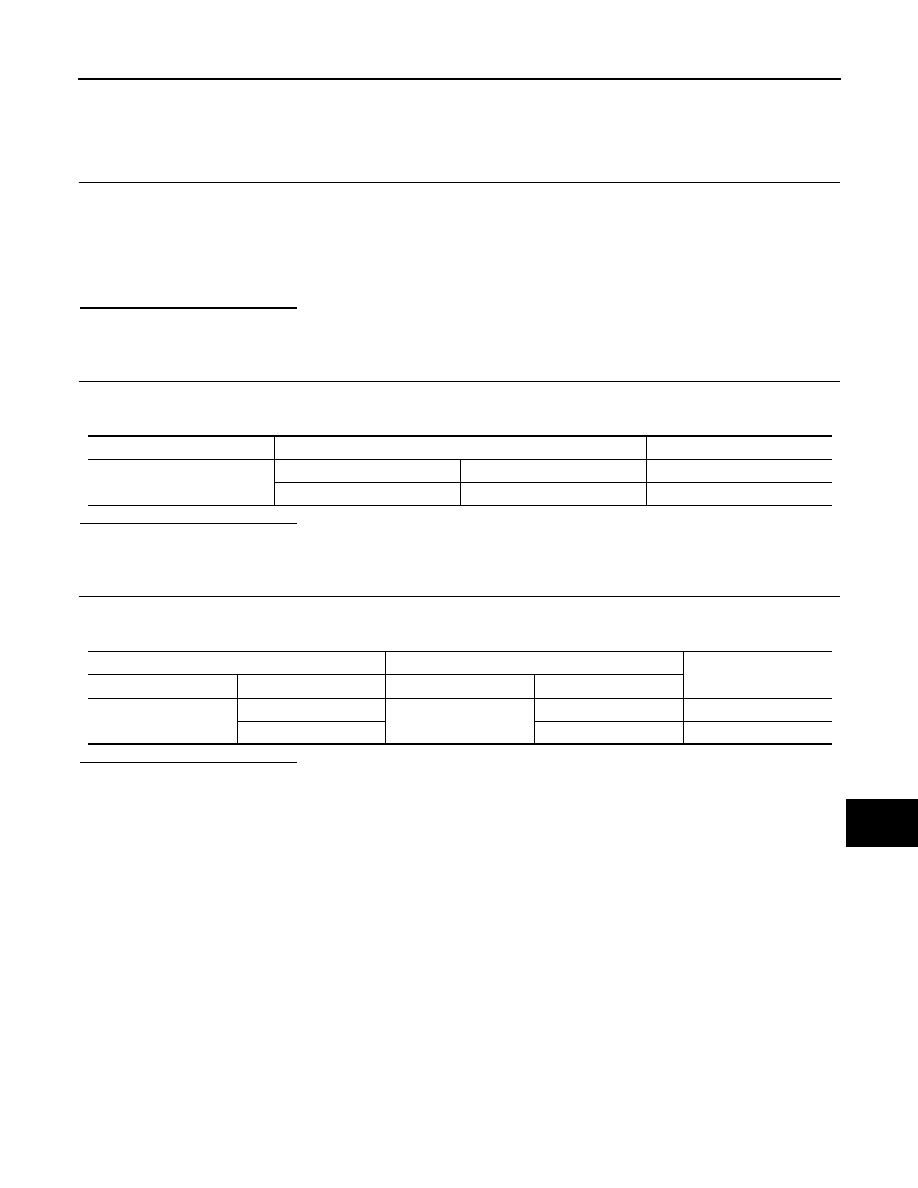
Check the continuity between the unified meter and A/C amp. harness connector and the harness con-
nector.
Is the inspection result normal?
YES
>> GO TO 3.
NO
>> Repair the main line between the unified meter and A/C amp. and the harness connector M7.
3.
CHECK HARNESS CONTINUITY (OPEN CIRCUIT)
Check the continuity between the harness connector terminals.
Is the inspection result normal?
YES (Present error)>>Check CAN system type decision again.
YES (Past error)>>Error was detected in the main line between the unified meter and A/C amp. and the
driver seat control unit.
NO
>> Repair the main line between the harness connector B1 and the driver seat control unit.
Unified meter and A/C amp. harness connector
Harness connector
Continuity
Connector No.
Terminal No.
Connector No.
Terminal No.
M67
56
M7
80
Existed
72
81
Existed
Connector No.
Terminal No.
Continuity
B1
80
82
Existed
81
83
Existed
LAN
MAIN LINE BETWEEN ADP AND CGW CIRCUIT
LAN-213
< DTC/CIRCUIT DIAGNOSIS >
[CAN SYSTEM (TYPE 6)]
C
D
E
F
G
H
I
J
K
L
B
A
O
P
N
MAIN LINE BETWEEN ADP AND CGW CIRCUIT
Diagnosis Procedure
INFOID:0000000005577073
1.
CHECK CONNECTOR
1.
Turn the ignition switch OFF.
2.
Disconnect the battery cable from the negative terminal.
3.
Check the following terminals and connectors for damage, bend and loose connection (connector side
and harness side).
-
Harness connector B1
-
Harness connector M7
Is the inspection result normal?
YES
>> GO TO 2.
NO
>> Repair the terminal and connector.
2.
CHECK HARNESS CONTINUITY (OPEN CIRCUIT)
1.
Disconnect the harness connectors B1 and M7.
2.
Check the continuity between the harness connector terminals.
Is the inspection result normal?
YES
>> GO TO 3.
NO
>> Repair the main line between the driver seat control unit and the harness connector B1.
3.
CHECK HARNESS CONTINUITY (OPEN CIRCUIT)
1.
Disconnect the connector of CAN gateway.
2.
Check the continuity between the harness connector M7 and the CAN gateway harness connector.
Is the inspection result normal?
YES (Present error)>>Check CAN system type decision again.
YES (Past error)>>Error was detected in the main line between the driver seat control unit and the CAN
gateway.
NO
>> Repair the main line between the harness connector M7 and the CAN gateway.
Connector No.
Terminal No.
Continuity
B1
82
80
Existed
83
81
Existed
Harness connector
CAN gateway harness connector
Continuity
Connector No.
Terminal No.
Connector No.
Terminal No.
M7
82
M125
1
Existed
83
7
Existed
Нет комментариевНе стесняйтесь поделиться с нами вашим ценным мнением.
Текст