Infiniti FX35, FX50 (S51). Manual — part 1697

IPDM E/R (INTELLIGENT POWER DISTRIBUTION MODULE ENGINE ROOM)
SEC-201
< ECU DIAGNOSIS INFORMATION >
[INTELLIGENT KEY SYSTEM]
C
D
E
F
G
H
I
J
L
M
A
B
SEC
N
O
P
43
(SB)
Ground
A/T shift selector
(Detention switch)
Input
Ignition
switch ON
• Press the selector but-
ton (Selector lever P)
• Selector lever in any po-
sition other than P
Battery voltage
Release the selector but-
ton (selector lever P)
0 V
44
(W)
Ground
Horn relay control
Input
The horn is deactivated
Battery voltage
The horn is activated
0 V
45
(G)
Ground
Anti theft horn relay control
Input
The horn is deactivated
Battery voltage
The horn is activated
0 V
46
(BR)
Ground
Starter relay control
Input
Ignition
switch ON
Selector lever in any posi-
tion other than P or N
0 V
Selector lever P or N
Battery voltage
48
(L)
Ground
A/C relay power supply
Output
Engine
running
A/C switch OFF
0 V
A/C switch ON
(A/C compressor is oper-
ating)
Battery voltage
49
(W)
*1
(SB)
*3
Ground
ECM relay power supply
Output
Ignition switch OFF
(More than a few seconds after turning
ignition switch OFF)
0 V
• Ignition switch ON
• Ignition switch OFF
(For a few seconds after turning igni-
tion switch OFF)
Battery voltage
51
(G)
Ground
Ignition relay power supply
Output
Ignition switch OFF
0 V
Ignition switch ON
Battery voltage
52
(W)
Ground
Ignition relay power supply
Output
Ignition switch OFF
0 V
Ignition switch ON
Battery voltage
53
(W)
Ground
ECM relay power supply
Output
Ignition switch OFF
(More than a few seconds after turning
ignition switch OFF)
0 V
• Ignition switch ON
• Ignition switch OFF
(For a few seconds after turning igni-
tion switch OFF)
Battery voltage
54
(R)
Ground
Throttle control motor re-
lay power supply
Output
Ignition switch OFF
(More than a few seconds after turning
ignition switch OFF)
0 V
• Ignition switch ON
• Ignition switch OFF
(For a few seconds after turning igni-
tion switch OFF)
Battery voltage
55
(BR)
Ground
ECM power supply
Output
Ignition switch OFF
Battery voltage
56
(O)
*1
(V)
*3
Ground
Ignition relay power supply
Output
Ignition switch OFF
0 V
Ignition switch ON
Battery voltage
57
(LG)
Ground
Ignition relay power supply
Output
Ignition switch OFF
0 V
Ignition switch ON
Battery voltage
Terminal No.
(Wire color)
Description
Condition
Value
(Approx.)
Signal name
Input/
Output
+
−
SEC-202
< ECU DIAGNOSIS INFORMATION >
[INTELLIGENT KEY SYSTEM]
IPDM E/R (INTELLIGENT POWER DISTRIBUTION MODULE ENGINE ROOM)
58
(Y)
Ground
Ignition relay power supply
Output
Ignition switch OFF
0 V
Ignition switch ON
Battery voltage
69
(W)
Ground
ECM relay control
Output
Ignition switch OFF
(More than a few seconds after turning
ignition switch OFF)
Battery voltage
• Ignition switch ON
• Ignition switch OFF
(For a few seconds after turning igni-
tion switch OFF)
0 – 1.5 V
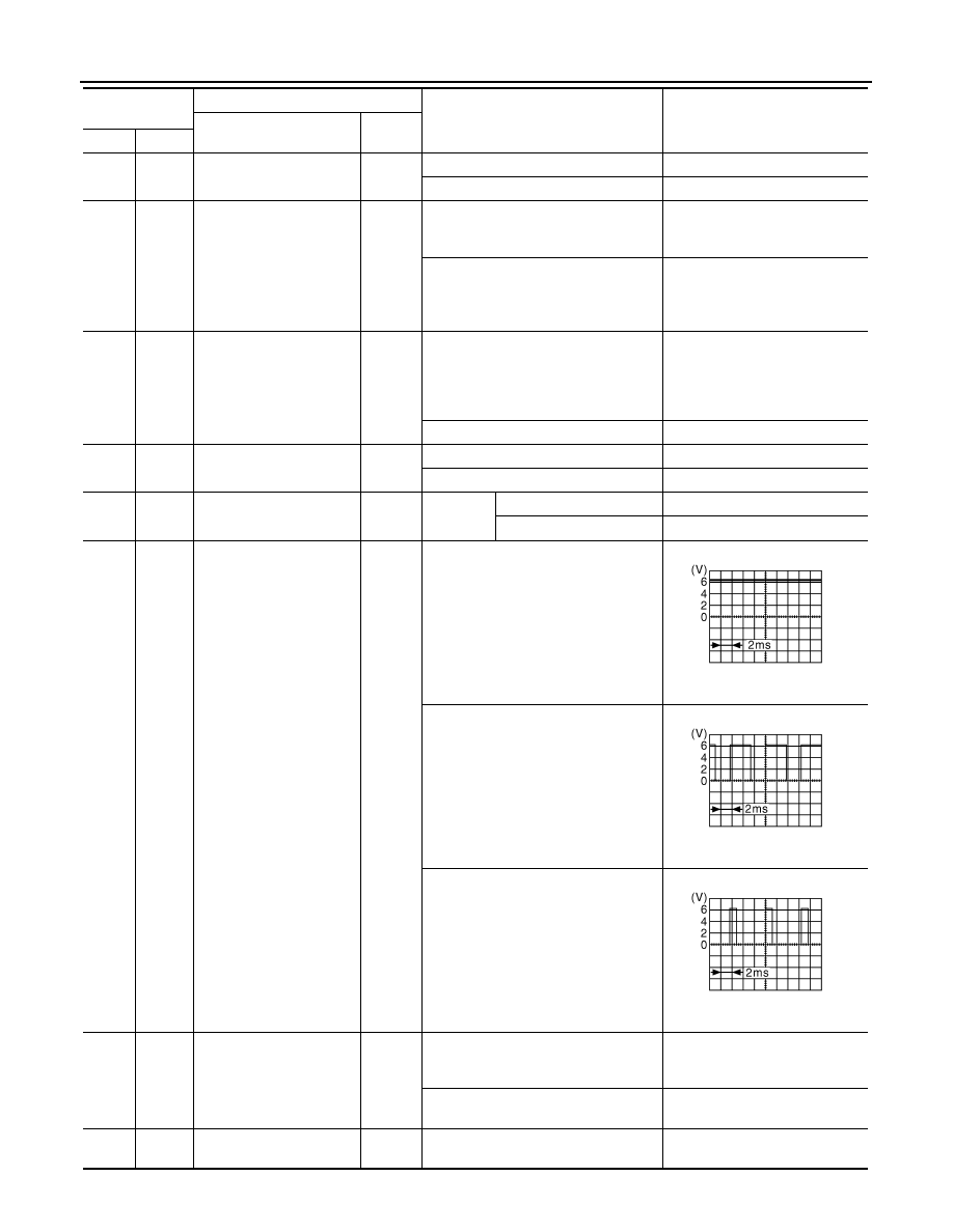
70
(O)
Ground
Throttle control motor re-
lay control
Output
Ignition switch ON
→
OFF
0 – 1.0 V
↓
Battery voltage
↓
0 V
Ignition switch ON
0 – 1.0 V
74
(G)
Ground
Ignition relay power supply
Output
Ignition switch OFF
0 V
Ignition switch ON
Battery voltage
75
(Y)
Ground
Oil pressure switch
Input
Ignition
switch ON
Engine stopped
0 V
Engine running
Battery voltage
76
(P)
*1
(V)
*3
Ground
Power generation com-
mand signal
Output
Ignition switch ON
6.3 V
40% is set on “ACTIVE TEST”, “AL-
TERNATOR DUTY” of “ENGINE”
3.8 V
80% is set on “ACTIVE TEST”, “AL-
TERNATOR DUTY” of “ENGINE”
1.4 V
77
(B)
*1
(L)
*3
Ground
Fuel pump relay control
Output
• Approximately 1 second after turning
the ignition switch ON
• Engine running
0 – 1.0 V
Approximately 1 second or more after
turning the ignition switch ON
Battery voltage
80
(W)
Ground
Starter motor
Output
At engine cranking
Battery voltage
Terminal No.
(Wire color)
Description
Condition
Value
(Approx.)
Signal name
Input/
Output
+
−
JPMIA0001GB
JPMIA0002GB
JPMIA0003GB

IPDM E/R (INTELLIGENT POWER DISTRIBUTION MODULE ENGINE ROOM)
SEC-203
< ECU DIAGNOSIS INFORMATION >
[INTELLIGENT KEY SYSTEM]
C
D
E
F
G
H
I
J
L
M
A
B
SEC
N
O
P
*1: VK engine models
*2: Only for the models with ICC system
*3: VQ engine models
83
(R)
Ground
Headlamp LO (RH)
Output
Ignition
switch ON
Lighting switch OFF
0 V
Lighting switch 2ND
Battery voltage
84
(P)
Ground
Headlamp LO (LH)
Output
Ignition
switch ON
Lighting switch OFF
0 V
Lighting switch 2ND
Battery voltage
86
(W)
Ground
Front fog lamp
Output
Lighting
switch
2ND
• Front fog lamp switch
ON
• Daytime running light
activated (Only for Can-
ada)
Battery voltage
Front fog lamp switch OFF
0 V
88
(G)
Ground
Washer pump power sup-
ply
Output
Ignition switch ON
Battery voltage
89
(BR)
Ground
Headlamp HI (RH)
Output
Ignition
switch ON
• Lighting switch HI
• Lighting switch PASS
Battery voltage
Lighting switch OFF
0 V
90
(Y)
Ground
Headlamp HI (LH)
Output
Ignition
switch ON
• Lighting switch HI
• Lighting switch PASS
Battery voltage
Lighting switch OFF
0 V
91
(P)
Ground
Parking lamp (RH)
Output
Ignition
switch ON
Lighting switch 1ST
Battery voltage
Lighting switch OFF
0 V
92
(O)
Ground
Parking lamp (LH)
Output
Ignition
switch ON
Lighting switch 1ST
Battery voltage
Lighting switch OFF
0 V
97
(V)
Ground
Cooling fan control
Output
Engine idling
0 – 5 V
104
(LG)
Ground
Hood switch
Input
Close the hood
Battery voltage
Open the hood
0 V
Terminal No.
(Wire color)
Description
Condition
Value
(Approx.)
Signal name
Input/
Output
+
−
SEC-204
< ECU DIAGNOSIS INFORMATION >
[INTELLIGENT KEY SYSTEM]
IPDM E/R (INTELLIGENT POWER DISTRIBUTION MODULE ENGINE ROOM)
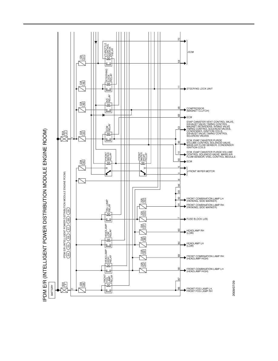
Wiring Diagram - IPDM E/R -
INFOID:0000000005683355
JCMWA4984GB
Нет комментариевНе стесняйтесь поделиться с нами вашим ценным мнением.
Текст