Infiniti FX35, FX50 (S51). Manual — part 1940
LOW TIRE PRESSURE WARNING LAMP BLINKS
WT-63
< SYMPTOM DIAGNOSIS >
C
D
F
G
H
I
J
K
L
M
A
B
WT
N
O
P
LOW TIRE PRESSURE WARNING LAMP BLINKS
Description
INFOID:0000000005549653
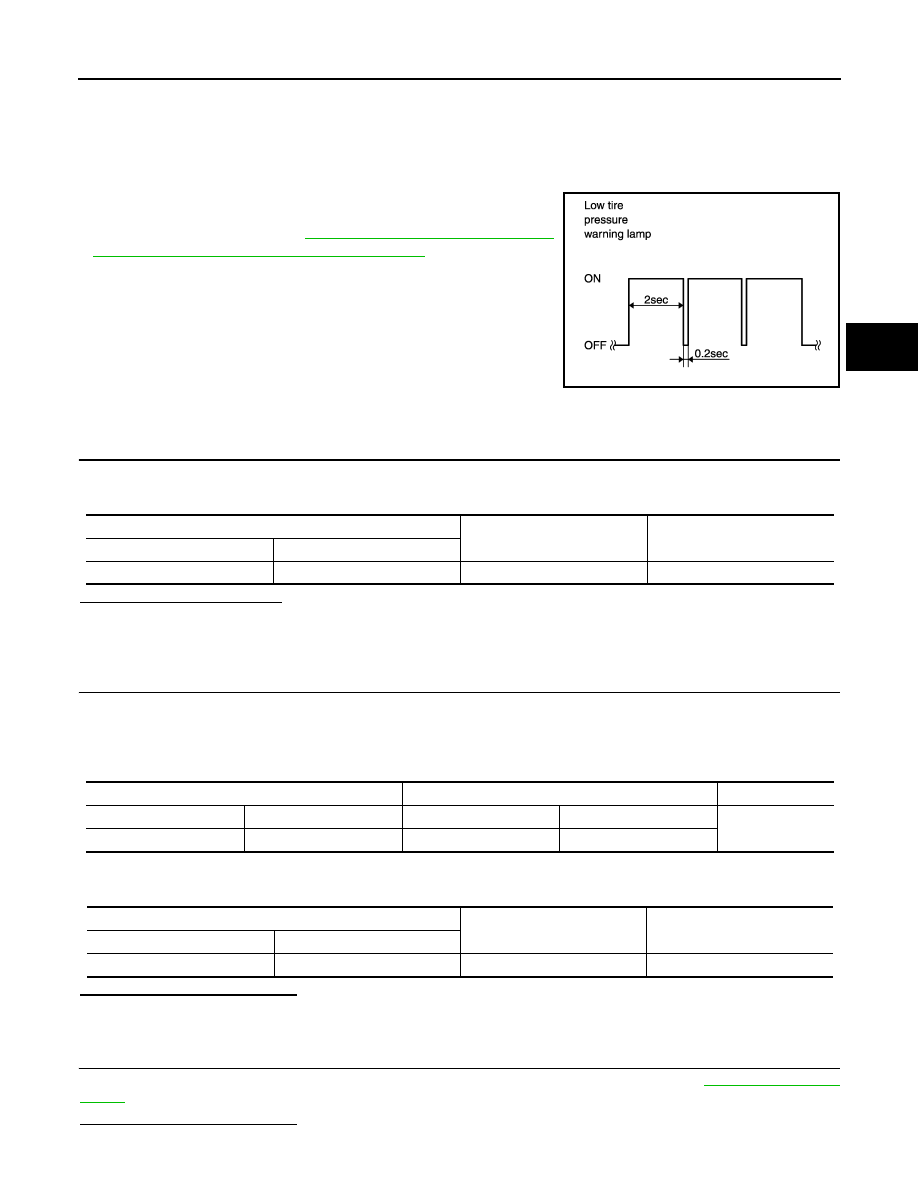
• The low tire pressure warning lamp blinks when the ignition switch is turned ON.
• Blinking mode
When the low tire pressure warning lamp blinks as shown in the
figure, the transmitter is not waked up. Perform the transmitter
wake-up operation. Refer to
OPERATION : Transmitter Wake-up Procedure"
.
Diagnosis Procedure
INFOID:0000000005549654
1.
CHECK POWER OF TIRE PRESSURE WARNING CHECK SWITCH CONNECTOR
1.
Turn the ignition switch ON.
2.
Check the voltage between the tire pressure warning check switch and the ground.
Is the output voltage normal?
YES
>> Repair or replace the low tire pressure warning control unit. Or, replace the low tire pressure warn-
ing control unit.
NO
>> GO TO 2.
2.
CHECK TIRE PRESSURE WARNING CHECK SWITCH CONNECTOR CIRCUIT
1.
Turn the ignition switch OFF.
2.
Disconnect the low tire pressure warning control unit harness connector.
3.
Check the continuity between the terminals of the low tire pressure warning control unit harness connec-
tor and the tire pressure warning check switch the connector.
4.
Check the continuity between the low tire pressure warning control unit harness connector and the
ground.
Is the inspection result normal?
YES
>> GO TO 3.
NO
>> Repair or replace error-detected parts.
3.
CHECK LOW TIRE PRESSURE WARNING CONTROL UNIT
Check the input/output signals of the low tire pressure warning control unit. Refer to
Is the inspection result normal?
JSEIA0033GB
Tire pressure warning check switch
—
Voltage
Connector
Terminal
M23
1
Ground
7.6 - 14.6 V
Low tire pressure warning control unit
Tire pressure warning check switch
Continuity
Connector
Terminal
Connector
Terminal
Existed
M96
12
M23
1
Low tire pressure warning control unit
—
Continuity
Connector
Terminal
M96
12
Ground
Not existed
WT-64
< SYMPTOM DIAGNOSIS >
LOW TIRE PRESSURE WARNING LAMP BLINKS
YES
>> Replace the low tire pressure warning control unit.
NO
>> GO TO 4.
4.
CHECK LOW TIRE PRESSURE WARNING CONTROL UNIT HARNESS CONNECTOR
Check for looseness or damage at the harness connector pins of the low tire pressure warning control unit.
Is the inspection result normal?
YES
>> INSPECTION END
NO
>> Repair or replace error-detected parts.
TURN SIGNAL LAMP BLINKS
WT-65
< SYMPTOM DIAGNOSIS >
C
D
F
G
H
I
J
K
L
M
A
B
WT
N
O
P
TURN SIGNAL LAMP BLINKS
Description
INFOID:0000000005549655
DESCRIPTION
The turn signal lamp blinks when the ignition switch is turned ON.
Diagnosis Procedure
INFOID:0000000005549656
1.
CHECK LOW TIRE PRESSURE WARNING CONTROL UNIT
1.
Check low tire pressure warning control unit input/output signal. Refer to
.
Is the inspection result normal?
YES
>> GO TO 3.
NO
>> GO TO 2.
2.
CHECK LOW TIRE PRESSURE WARNING CONTROL UNIT CIRCUIT
With CONSULT-III
Perform “AIR PRESSURE MONITOR” self-diagnosis. Refer to
.
Is the inspection result normal?
YES
>> GO TO 3.
NO
>> Repair or replace error-detected parts.
3.
CHECK TIRE PRESSURE WARNING CONTROL UNIT AND BCM CIRCUIT
1.
Turn the ignition switch OFF.
2.
Disconnect low tire pressure warning control unit harness connector and BCM harness connector.
3.
Check the continuity between low tire pressure warning control unit harness connector and BCM harness
connector.
Is the inspection result normal?
YES
>> Check the BCM. Refer to
BCS-4, "CONFIGURATION (BCM) : Work Procedure"
NO
>> Repair or replace error-detected parts.
Low tire pressure warning control unit
BCM
Continuity
Connector
Terminal
Connector
Terminal
M96
30
M122
110
Existed
WT-66
< SYMPTOM DIAGNOSIS >
ID REGISTRATION CANNOT BE COMPLETED
ID REGISTRATION CANNOT BE COMPLETED
Description
INFOID:0000000005549657
DESCRIPTION
The ID of the transmitter installed in each wheel cannot be registered in the tire pressure monitoring system.
Inspect the transmitter or the tire pressure monitoring system circuit.
Diagnosis Procedure
INFOID:0000000005549658
1.
CHECK ID REGISTRATION
1.
Perform ID registration of all transmitters. Refer to
WT-7, "ID REGISTRATION PROCEDURE : Transmit-
ter ID Registration Procedure"
2.
Drive at a speed of 40 km/h (25 MPH) or more for 3 minutes, and then drive the vehicle at any speed for
10 minutes.
3.
Within 5 minutes, select “DATA MONITOR”of “AIR PRESSURE MONITOR” and display the tire pressure
for all wheels.
4.
Check that the displayed tire pressure is the specified value.
Is the inspection result normal?
YES
>> INSPECTION END
NO
>> GO TO 2.
2.
CHECK TRANSMITTER
1.
Perform trouble diagnosis for transmitters. Refer to
2.
Perform ID registration of all transmitters. Refer to
WT-7, "ID REGISTRATION PROCEDURE : Transmit-
ter ID Registration Procedure"
Can ID registration of all transmitters be completed?
YES
>> INSPECTION END
NO
>> Replace the transmitter. Refer to
.
Monitored item
Condition
Display value
AIR PRESS FL
Start the engine and drive at a speed of 40 km/h (25
MPH) or more for several minutes.
Approximately equal to the indication on vehicle
information display.
AIR PRESS FR
AIR PRESS RR
AIR PRESS RL
Нет комментариевНе стесняйтесь поделиться с нами вашим ценным мнением.
Текст