Infiniti FX35, FX50 (S51). Manual — part 1336
LAN-286
< DTC/CIRCUIT DIAGNOSIS >
[CAN SYSTEM (TYPE 9)]
ECM BRANCH LINE CIRCUIT
ECM BRANCH LINE CIRCUIT
Diagnosis Procedure
INFOID:0000000005577195
1.
CHECK CONNECTOR
1.
Turn the ignition switch OFF.
2.
Disconnect the battery cable from the negative terminal.
3.
Check the terminals and connectors of the ECM for damage, bend and loose connection (unit side and
connector side).
Is the inspection result normal?
YES
>> GO TO 2.
NO
>> Repair the terminal and connector.
2.
CHECK HARNESS FOR OPEN CIRCUIT
1.
Disconnect the connector of ECM.
2.
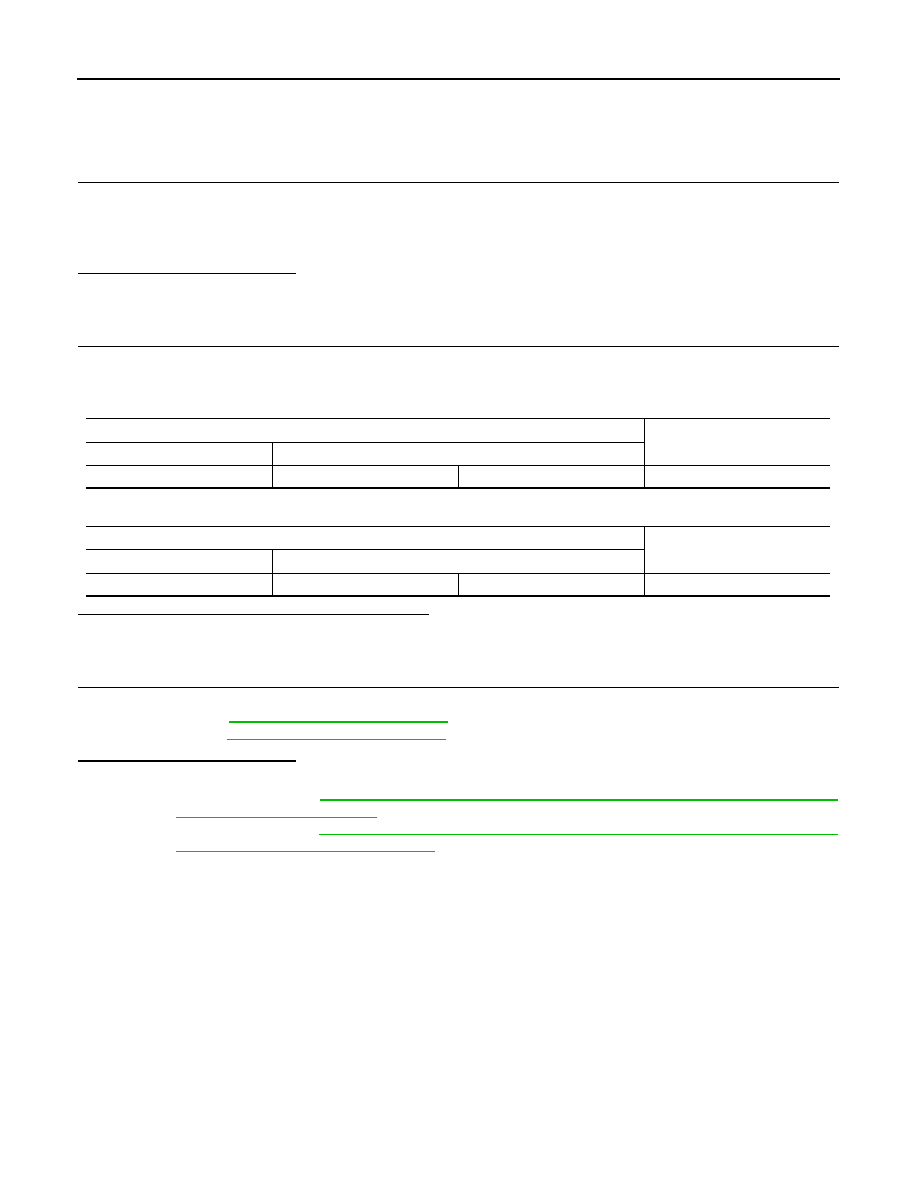
Check the resistance between the ECM harness connector terminals.
-
VQ engine models
-
VK engine models
Is the measurement value within the specification?
YES
>> GO TO 3.
NO
>> Repair the ECM branch line.
3.
CHECK POWER SUPPLY AND GROUND CIRCUIT
Check the power supply and the ground circuit of the ECM. Refer to the following.
• VQ engine models:
• VK engine models:
Is the inspection result normal?
YES (Present error)>>Replace the ECM. Refer to the following.
• VQ engine models:
EC-23, "ADDITIONAL SERVICE WHEN REPLACING CONTROL UNIT :
EC-579, "ADDITIONAL SERVICE WHEN REPLACING CONTROL UNIT
(ECM) : Special Repair Requirement"
YES (Past error)>>Error was detected in the ECM branch line.
NO
>> Repair the power supply and the ground circuit.
ECM harness connector
Resistance (
Ω
)
Connector No.
Terminal No.
M107
114
113
Approx. 108 – 132
ECM harness connector
Resistance (
Ω
)
Connector No.
Terminal No.
M160
105
101
Approx. 108 – 132
LAN
4WD BRANCH LINE CIRCUIT
LAN-287
< DTC/CIRCUIT DIAGNOSIS >
[CAN SYSTEM (TYPE 9)]
C
D
E
F
G
H
I
J
K
L
B
A
O
P
N
4WD BRANCH LINE CIRCUIT
Diagnosis Procedure
INFOID:0000000005577196
1.
CHECK CONNECTOR
1.
Turn the ignition switch OFF.
2.
Disconnect the battery cable from the negative terminal.
3.
Check the terminals and connectors of the AWD control unit for damage, bend and loose connection (unit
side and connector side).
Is the inspection result normal?
YES
>> GO TO 2.
NO
>> Repair the terminal and connector.
2.
CHECK HARNESS FOR OPEN CIRCUIT
1.
Disconnect the connector of AWD control unit.
2.
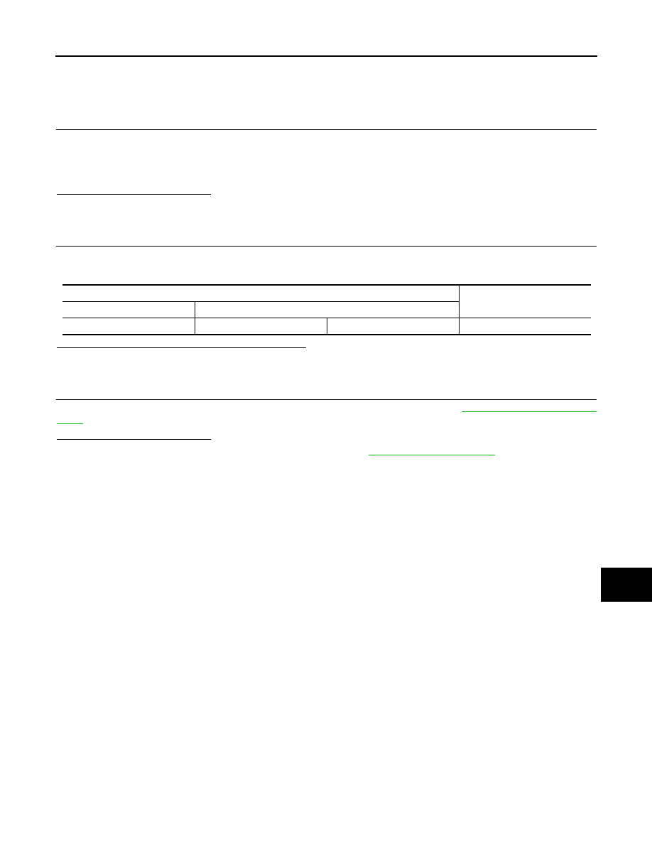
Check the resistance between the AWD control unit harness connector terminals.
Is the measurement value within the specification?
YES
>> GO TO 3.
NO
>> Repair the AWD control unit branch line.
3.
CHECK POWER SUPPLY AND GROUND CIRCUIT
Check the power supply and the ground circuit of the AWD control unit. Refer to
.
Is the inspection result normal?
YES (Present error)>>Replace the AWD control unit. Refer to
YES (Past error)>>Error was detected in the AWD control unit branch line.
NO
>> Repair the power supply and the ground circuit.
AWD control unit harness connector
Resistance (
Ω
)
Connector No.
Terminal No.
M105
8
16
Approx. 54 – 66
LAN-288
< DTC/CIRCUIT DIAGNOSIS >
[CAN SYSTEM (TYPE 9)]
DLC BRANCH LINE CIRCUIT
DLC BRANCH LINE CIRCUIT
Diagnosis Procedure
INFOID:0000000005577197
1.
CHECK CONNECTOR
1.
Turn the ignition switch OFF.
2.
Disconnect the battery cable from the negative terminal.
3.
Check the terminals and connectors of the data link connector for damage, bend and loose connection
(connector side and harness side).
Is the inspection result normal?
YES
>> GO TO 2.
NO
>> Repair the terminal and connector.
2.
CHECK HARNESS FOR OPEN CIRCUIT
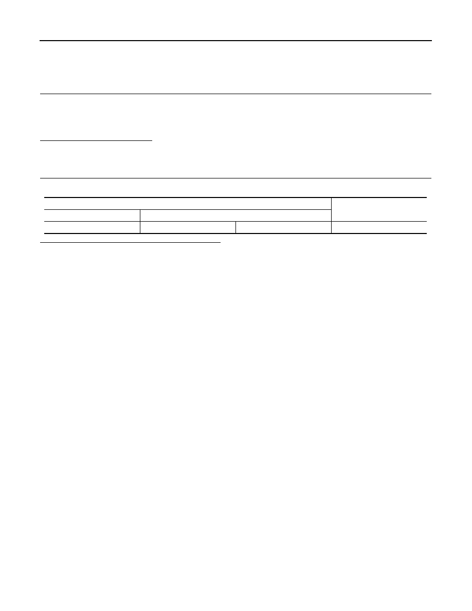
Check the resistance between the data link connector terminals.
Is the measurement value within the specification?
YES (Present error)>>Check CAN system type decision again.
YES (Past error)>>Error was detected in the data link connector branch line circuit.
NO
>> Repair the data link connector branch line.
Data link connector
Resistance (
Ω
)
Connector No.
Terminal No.
M24
6
14
Approx. 54 – 66
LAN
TCM BRANCH LINE CIRCUIT
LAN-289
< DTC/CIRCUIT DIAGNOSIS >
[CAN SYSTEM (TYPE 9)]
C
D
E
F
G
H
I
J
K
L
B
A
O
P
N
TCM BRANCH LINE CIRCUIT
Diagnosis Procedure
INFOID:0000000005577198
1.
CHECK CONNECTOR
1.
Turn the ignition switch OFF.
2.
Disconnect the battery cable from the negative terminal.
3.
Check the following terminals and connectors for damage, bend and loose connection (unit side and con-
nector side).
-
A/T assembly
-
Harness connector F103
-
Harness connector M116
Is the inspection result normal?
YES
>> GO TO 2.
NO
>> Repair the terminal and connector.
2.
CHECK HARNESS FOR OPEN CIRCUIT
1.
Disconnect the connector of A/T assembly.
2.
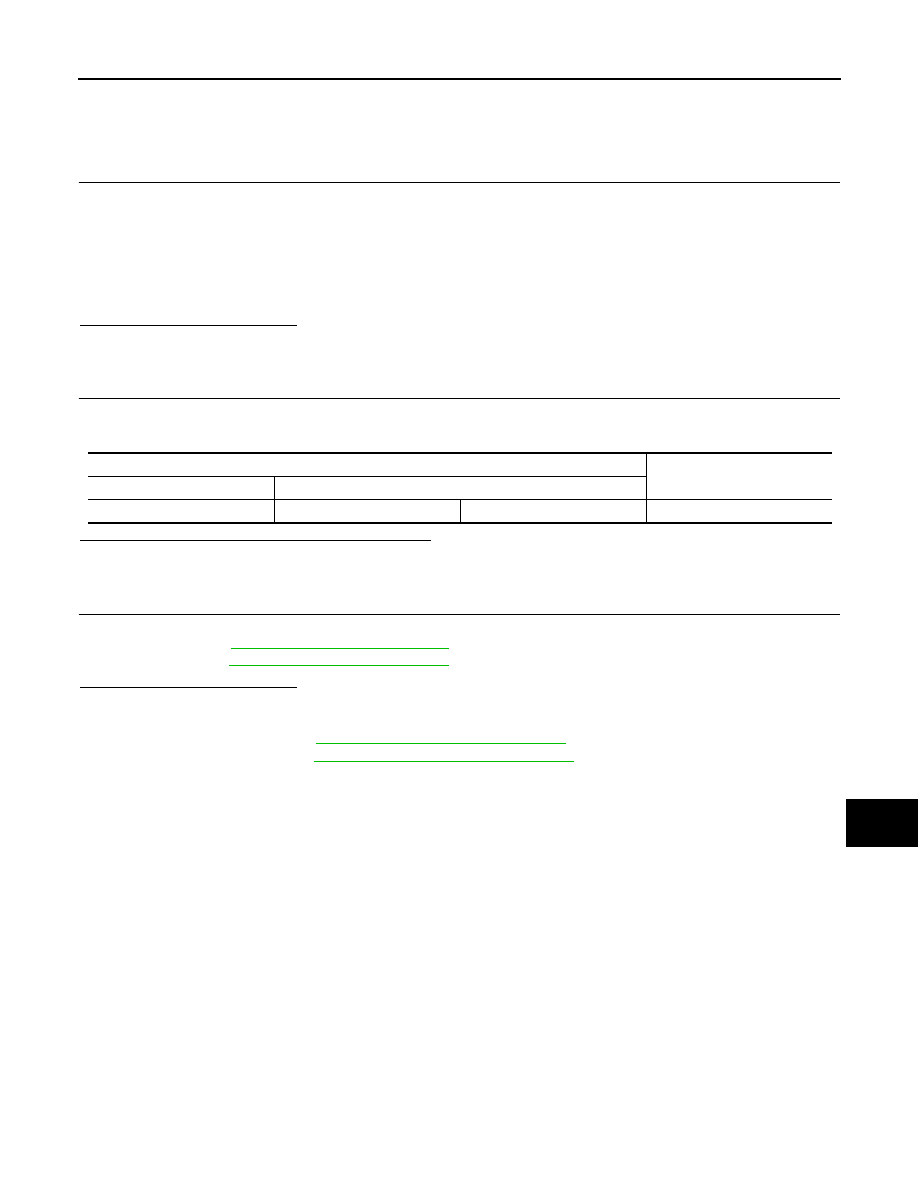
Check the resistance between the A/T assembly harness connector terminals.
Is the measurement value within the specification?
YES
>> GO TO 3.
NO
>> Repair the TCM branch line.
3.
CHECK POWER SUPPLY AND GROUND CIRCUIT
Check the power supply and the ground circuit of the TCM. Refer to the following.
• VQ engine models:
• VK engine models:
Is the inspection result normal?
YES (Present error)>>Replace the control valve with TCM. (Replace A/T assembly if control valve with TCM
is not listed in the latest parts list.) Refer to the following.
• VQ engine models:
TM-11, "Component Parts Location"
• VK engine models:
TM-193, "Component Parts Location"
YES (Past error)>>Error was detected in the TCM branch line.
NO
>> Repair the power supply and the ground circuit.
A/T assembly harness connector
Resistance (
Ω
)
Connector No.
Terminal No.
F51
3
8
Approx. 54 – 66
Нет комментариевНе стесняйтесь поделиться с нами вашим ценным мнением.
Текст