Infiniti FX35, FX50 (S51). Manual — part 107

AV
AV CONTROL UNIT
AV-201
< ECU DIAGNOSIS INFORMATION >
[NAVIGATION (SINGLE MONITOR)]
C
D
E
F
G
H
I
J
K
L
M
B
A
O
P
U1310
CONTROL UNIT (AV) [U1310]
U1300
U1240
• AV COMM CIRCUIT [U1300]
• SWITCH CONN [U1240]
U1300
U125B
• AV COMM CIRCUIT [U1300]
• AROUND CAMERA CONN [U125B]
U1300
U125C
• AV COMM CIRCUIT [U1300]
• SONAR CONN [U125C]
U1300
U1240
U125B
• AV COMM CIRCUIT [U1300]
• SWITCH CONN [U1240]
• AROUND CAMERA CONN [U125B]
DTC
Display item
Refer to
AV-202
< ECU DIAGNOSIS INFORMATION >
[NAVIGATION (SINGLE MONITOR)]
FRONT DISPLAY UNIT
FRONT DISPLAY UNIT
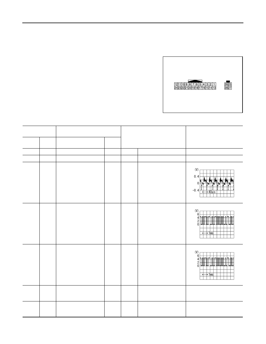
Reference Value
INFOID:0000000005475067
TERMINAL LAYOUT
PHYSICAL VALUES
JSNIA2241ZZ
Terminal
(Wire color)
Description
Condition
Reference value
(Approx.)
+
–
Signal name
Input/
Output
6
—
Shield
—
—
—
—
7
—
Shield
—
—
—
—
8
(W)
Ground
Camera image signal
Input
Ignition
switch
ON
At camera image is dis-
played.
9
(G)
Ground
Communication signal
(DISP
→
CONT)
Output
Ignition
switch
ON
When adjusting display
brightness.
10
(R)
Ground
Communication signal
(CONT
→
DISP)
Input
Ignition
switch
ON
When adjusting display
brightness.
11
(P)
Ground
Battery power supply
Input
Ignition
switch
OFF
—
Battery voltage
12
(B)
Ground
Ground
—
Ignition
switch
ON
—
0 V
SKIB2251J
PKIB5039J
PKIB5039J
AV
FRONT DISPLAY UNIT
AV-203
< ECU DIAGNOSIS INFORMATION >
[NAVIGATION (SINGLE MONITOR)]
C
D
E
F
G
H
I
J
K
L
M
B
A
O
P
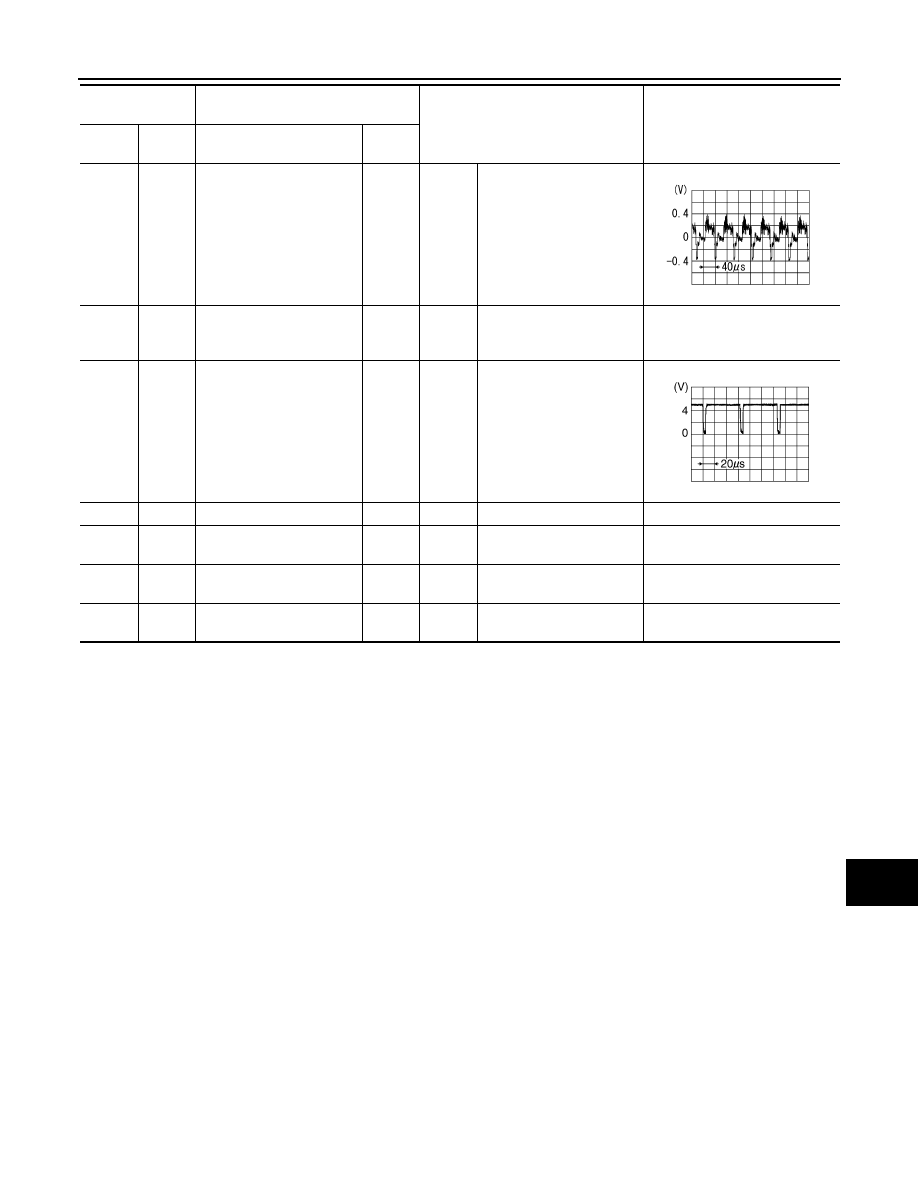
18
(R)
Ground
Composite image signal
Input
Ignition
switch
ON
At DVD image is displayed.
19
(B)
Ground
Composite image signal
ground
—
Ignition
switch
ON
—
0 V
20
(W)
Ground
Composite image synchro-
nizing signal
Input
Ignition
switch
ON
—
22
—
Shield
—
—
—
—
23
(L)
Ground
ACC power supply
Input
—
—
—
27
—
RGB digital image signal
(
−
)
Input
—
—
—
28
—
RGB digital image signal
(+)
Input
—
—
—
Terminal
(Wire color)
Description
Condition
Reference value
(Approx.)
+
–
Signal name
Input/
Output
SKIB2251J
SKIB0825E
AV-204
< ECU DIAGNOSIS INFORMATION >
[NAVIGATION (SINGLE MONITOR)]
BOSE AMP.
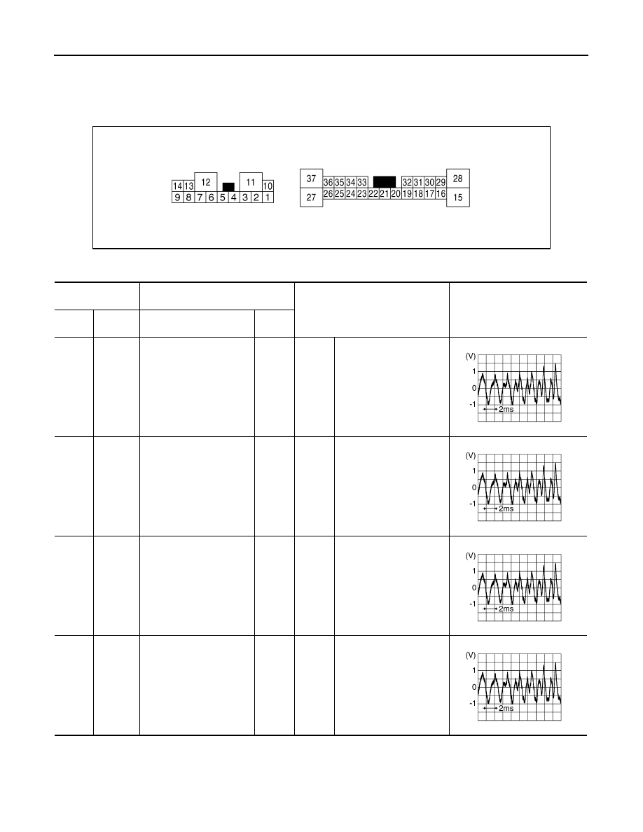
BOSE AMP.
Reference Value
INFOID:0000000005475072
TERMINAL LAYOUT
PHYSICAL VALUES
JSNIA0760ZZ
Terminal
(Wire color)
Description
Condition
Reference value
(Approx.)
+
–
Signal name
Input/
Output
1
(Y)
10
(G)
Sound signal rear door
speaker LH
Output
Ignition
switch
ON
Sound output
2
(SB)
3
(V)
Sound signal rear door
speaker RH
Output
Ignition
switch
ON
Sound output
4
(L)
5
(P)
Sound signal front door
speaker LH
Output
Ignition
switch
ON
Sound output
6
(O)
7
(W)
Sound signal front squawk-
er LH
Output
Ignition
switch
ON
Sound output
SKIB3609E
SKIB3609E
SKIB3609E
SKIB3609E
Нет комментариевНе стесняйтесь поделиться с нами вашим ценным мнением.
Текст