Infiniti FX35, FX50 (S51). Manual — part 1207
INL-28
< DTC/CIRCUIT DIAGNOSIS >
INTERIOR ROOM LAMP POWER SUPPLY CIRCUIT
INTERIOR ROOM LAMP POWER SUPPLY CIRCUIT
Description
INFOID:0000000005245561
BCM provides the step lamp power supply. Also BCM outputs it as the battery saver signal to total illumination
control unit. And BCM cuts the power supply when the interior room lamp battery saver is activated.
Diagnosis Procedure
INFOID:0000000005245562
1.
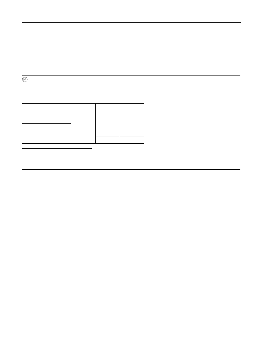
CHECK INTERIOR ROOM LAMP POWER SUPPLY OUTPUT
CONSULT-III ACTIVE TEST
1.
Turn ignition switch ON.
2.
Select “BATTERY SAVER” of BCM (BATTERY SAVER) active test item.
3.
While operating the test item, check voltage between BCM harness connector and ground.
Is the measurement value normal?
YES
>> GO TO 2.
NO
>> GO TO 3.
2.
CHECK INTERIOR ROOM LAMP POWER SUPPLY CIRCUIT FOR OPEN
1.
Turn ignition switch OFF.
2.
Disconnect the following connectors.
-
BCM
-
Total illumination control unit
-
Step lamp (Driver side)
-
Step lamp (Passenger side)
-
Step lamp (Rear LH)
-
Step lamp (Rear RH)
-
Luggage room lamp (Luggage side)
-
Luggage room lamp (Back door side)
3.
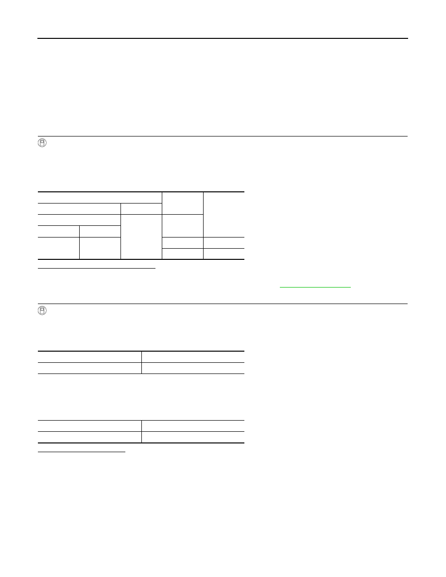
Check continuity between BCM harness connector and each interior room lamp harness connector.
Terminals
Test item
Voltage
(Approx.)
(+)
(
−
)
BCM
Ground
BATTERY
SAVER
Connector
Terminal
M119
4
Off
0 V
On
12 V

INTERIOR ROOM LAMP POWER SUPPLY CIRCUIT
INL-29
< DTC/CIRCUIT DIAGNOSIS >
C
D
E
F
G
H
I
J
K
M
A
B
INL
N
O
P
Does continuity exist?
YES
>> Interior room lamp power supply circuit is normal.
NO
>> Repair the harnesses or connectors.
3.
CHECK INTERIOR ROOM LAMP POWER SUPPLY CIRCUIT FOR SHORT
1.
Turn ignition switch OFF.
2.
Disconnect the following connectors.
-
BCM
-
Total illumination control unit
-
Step lamp (Driver side)
-
Step lamp (Passenger side)
-
Step lamp (Rear LH)
-
Step lamp (Rear RH)
-
Luggage room lamp (Luggage side)
-
Luggage room lamp (Back door side)
3.
Check continuity between BCM harness connector and ground.
Does continuity exist?
YES
>> Repair the harnesses or connectors.
NO
>> Replace BCM.
BCM
Each interior room lamp and total illumina-
tion control unit
Continu-
ity
Connec-
tor
Terminal
Connector
Terminal
M119
4
Total illumination
control unit
M129
6
Existed
Step lamp
(Driver side)
D12
1
Step lamp
(Passenger side)
D42
1
Step lamp
(Rear LH)
D59
1
Step lamp
(Rear RH)
D79
1
Luggage room lamp
(Luggage side)
B229
2
Luggage room lamp
(Back door side)
D110
2
BCM
Ground
Continuity
Connector
Terminal
M119
4
Not existed
INL-30
< DTC/CIRCUIT DIAGNOSIS >
BATTERY SAVER SIGNAL CIRCUIT
BATTERY SAVER SIGNAL CIRCUIT
Description
INFOID:0000000005245563
BCM cuts the interior room lamp power supply depending on the vehicle condition. Total illumination control
unit cuts the hospitality lighting power supply according to interior room lamp power supply (battery saver sig-
nal). This function prevents the battery from over-discharging if the driver neglects turning OFF any lamps.
Diagnosis Procedure
INFOID:0000000005245564
1.
CHECK BATTERY SAVER SIGNAL INPUT
CONSULT-III ACTIVE TEST
1.
Turn ignition switch ON.
2.
Select “BATTERY SAVER” of BCM (BATTERY SAVER) active test item.
3.
While operating the test item, check voltage between total illumination control unit harness connector and
ground.
Is the measurement value normal?
YES
>> GO TO 2.
NO
>> Check the interior room lamp power supply circuit. Refer to
2.
CHECK BATTERY SAVER SIGNAL BY CONSULT-III
CONSULT-III DATA MONITOR
1.
Turn ignition switch ON.
2.
Select “BAT SAVER SIGNAL” of TOTAL ILLUM C/U data monitor item.
3.
Check the monitor status.
4.
Turn ignition switch OFF.
5.
Disconnect the BCM (M119) connector.
6.
Turn ignition switch ON.
7.
Check the monitor status.
Is the item status normal?
YES
>> Battery saver signal circuit is normal.
NO
>> Replace the total illumination control unit.
Terminals
Test item
Voltage
(Approx.)
(+)
(
−
)
Total illumination control unit
Ground
BATTERY
SAVER
Connector
Terminal
M129
6
Off
0 V
On
12 V
Monitor item
Monitor status
BAT SAVER SIGNAL
On
Monitor item
Monitor status
BAT SAVER SIGNAL
Off
HOSPITALITY LIGHTING POWER SUPPLY CIRCUIT 1
INL-31
< DTC/CIRCUIT DIAGNOSIS >
C
D
E
F
G
H
I
J
K
M
A
B
INL
N
O
P
HOSPITALITY LIGHTING POWER SUPPLY CIRCUIT 1
Description
INFOID:0000000005245565
Total illumination control unit provides the following lamps power supply according to the battery saver signal
from BCM.
• Mood lamps (rear door armrest)
• Foot lamps
• Map lamps
• Center console indirect illumination (Ambience lamp)
• Personal lamps
• Vanity mirror lamps
• Push-button ignition switch illumination
Diagnosis Procedure
INFOID:0000000005245566
CAUTION:
Check the following circuit first if the other room lamps (Puddle lamps, push-button ignition switch
illumination, etc.) are not turned ON.
• Power supply and ground circuit of total illumination control unit: Refer to
NATION CONTROL UNIT : Diagnosis Procedure"
.
• Battery saver signal circuit: Refer to
1.
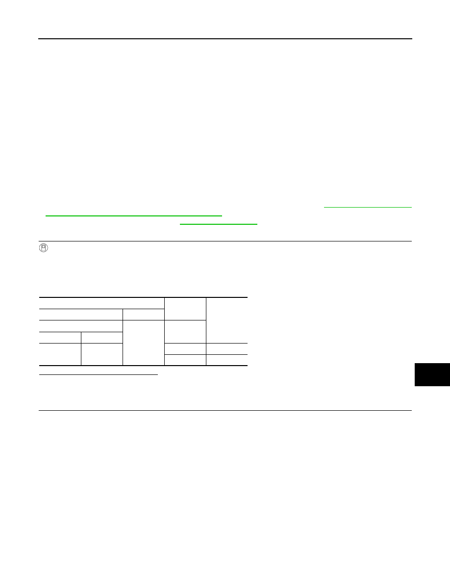
CHECK HOSPITALITY LIGHTING POWER SUPPLY 1 OUTPUT
CONSULT-III ACTIVE TEST
1.
Turn ignition switch ON.
2.
Select “BATTERY SAVER” of BCM (BATTERY SAVER) active test item.
3.
While operating the test item, check voltage between total illumination control unit harness connector and
ground.
Is the measurement value normal?
YES
>> GO TO 2.
NO
>> GO TO 4.
2.
CHECK HOSPITALITY LIGHTING POWER SUPPLY 1 CIRCUIT FOR OPEN
1.
Turn ignition switch OFF.
2.
Disconnect the following connectors.
-
Total illumination control unit
-
Roof module
-
Foot lamp (driver side)
-
Foot lamp (passenger side)
-
Mood lamp (rear door armrest LH)
-
Mood lamp (rear door armrest RH)
-
Push-button ignition switch
3.
Check continuity between total illumination control unit harness connector and each lamp harness con-
nectors.
Terminals
Test item
Voltage
(Approx.)
(+)
(
−
)
Total illumination control unit
Ground
BATTERY
SAVER
Connector
Terminal
M129
35
Off
0 V
On
12 V
Нет комментариевНе стесняйтесь поделиться с нами вашим ценным мнением.
Текст