Infiniti FX35, FX50 (S51). Manual — part 28

ADP-104
< DTC/CIRCUIT DIAGNOSIS >
MIRROR SENSOR
MIRROR SENSOR
DRIVER SIDE
DRIVER SIDE : Description
INFOID:0000000005249744
• The mirror sensor (driver side) is installed to the door mirror (driver side).
• The resistance of 2 sensors (horizontal and vertical) is changed when the door mirror (driver side) is oper-
ated.
• Automatic drive positioner control unit calculates the door mirror position according to the change of the volt-
age of 2 sensor input terminals.
DRIVER SIDE : Component Function Check
INFOID:0000000005249745
1.
CHECK FUNCTION
1.
Turn ignition switch ON.
2.
Select “MIR/SEN LH U-D”, “MIR/SEN LH R-L” in “Data monitor” with CONSULT-III.
3.
Check mirror sensor (driver side) signal under the following condition.
Is the indication normal?
YES
>> INSPECTION END
NO
>> Perform diagnosis procedure. Refer to
ADP-104, "DRIVER SIDE : Diagnosis Procedure"
.
DRIVER SIDE : Diagnosis Procedure
INFOID:0000000005249746
1.
CHECK DOOR MIRROR (DRIVER SIDE) SENSOR POWER SUPPLY
1.
Turn ignition switch OFF.
2.
Disconnect door mirror (driver side) connector.
3.
Turn ignition switch ON.
4.
Check voltage between door mirror (driver side) harness connector and ground.
Is the inspection result normal?
YES
>> GO TO 3.
NO
>> GO TO 2.
2.
CHECK DOOR MIRROR (DRIVER SIDE) SENSOR POWER SUPPLY CIRCUIT
1.
Turn ignition switch OFF.
2.
Disconnect automatic drive positioner control unit connector.
3.
Check continuity between automatic drive positioner control unit harness connector and door mirror
(driver side) harness connector.
4.
Check continuity between automatic drive positioner control unit harness connector and ground.
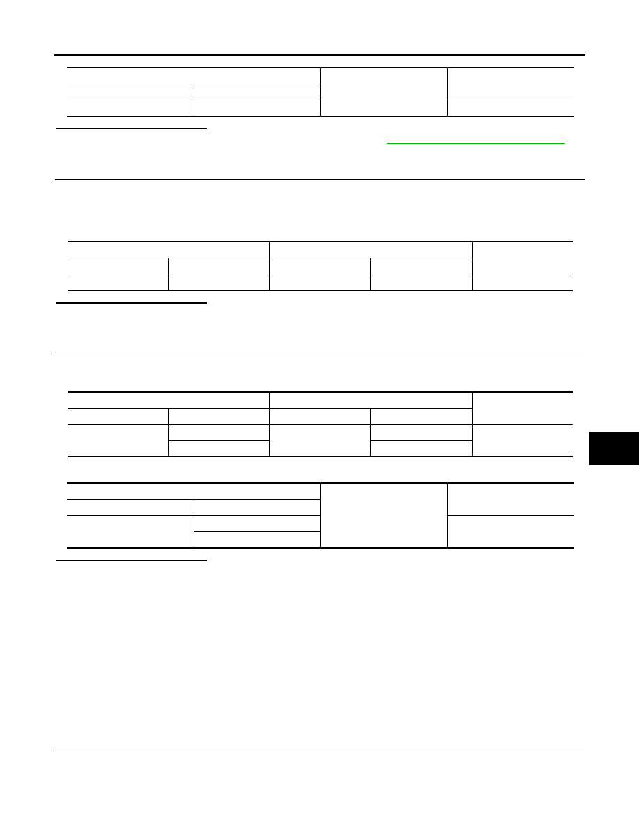
Monitor item
Condition
Value
MIR/SEN LH U-D
Door mirror (driver side)
Change between
3.4 [V] (close to peak)
0.6 [V] (close to valley)
MIR/SEN LH R-L
Change between
0.6 [V] (close to left edge)
3.4 [V] (close to right edge)
(+)
(–)
Voltage (V)
(Approx.)
Door mirror (driver side)
Connector
Terminal
D3
23
Ground
5
Automatic drive positioner
control unit connector
Terminal
Door mirror (driver side)
connector
Terminal
Continuity
M52
33
D3
23
Existed
MIRROR SENSOR
ADP-105
< DTC/CIRCUIT DIAGNOSIS >
C
D
E
F
G
H
I
K
L
M
A
B
ADP
N
O
P
Is the inspection result normal?
YES
>> Replace automatic drive positioner control unit. Refer to
ADP-216, "Removal and Installation"
.
NO
>> Repair or replace harness.
3.
CHECK DOOR MIRROR (DRIVER SIDE) SENSOR GROUND
1.
Turn ignition switch OFF.
2.
Disconnect automatic drive positioner control unit connector.
3.
Check continuity between automatic drive positioner control unit harness connector and door mirror
(driver side) harness connector.
Is the inspection result normal?
YES
>> GO TO 4.
NO
>> Repair or replace harness.
4.
CHECK DOOR MIRROR (DRIVER SIDE) SENSOR CIRCUIT
1.
Check continuity between automatic drive positioner control unit harness connector and door mirror
(driver side) harness connector.
2.
Check continuity between automatic drive positioner control unit harness connector and ground.
Is the inspection result normal?
YES
>> Replace door mirror sensor. (Built in driver side mirror.)
NO
>> Repair or replace harness.
PASSENGER SIDE
PASSENGER SIDE : Description
INFOID:0000000005249747
• The mirror sensor (passenger side) is installed to the door mirror (passenger side).
• The resistance of 2 sensors (horizontal and vertical) is changed when the door mirror (passenger side) is
operated.
• Automatic drive positioner control unit calculates the door mirror position according to the change of the volt-
age of 2 sensor input terminals.
PASSENGER SIDE : Component Function Check
INFOID:0000000005249748
1.
CHECK FUNCTION
1.
Turn ignition switch ON.
2.
Select “MIR/SEN RH U-D”, “MIR/SEN RH R-L” in “Data monitor” with CONSULT-III.
3.
Check the mirror sensor (passenger side) signal under the following conditions.
Automatic drive positioner control unit
Ground
Continuity
Connector
Terminal
M52
33
Not existed
Automatic drive positioner control unit
Door mirror (driver side)
Continuity
Connector
Terminal
Connector
Terminal
M52
41
D3
24
Existed
Automatic drive positioner control unit
Door mirror (driver side)
Continuity
Connector
Terminal
Connector
Terminal
M51
6
D3
21
Existed
22
22
Automatic drive positioner control unit
Ground
Continuity
Connector
Terminal
M51
6
Not existed
22

ADP-106
< DTC/CIRCUIT DIAGNOSIS >
MIRROR SENSOR
Is the indication normal?
YES
>> INSPECTION END
NO
>> Perform diagnosis procedure. Refer to
ADP-106, "PASSENGER SIDE : Diagnosis Procedure"
.
PASSENGER SIDE : Diagnosis Procedure
INFOID:0000000005249749
1.
CHECK DOOR MIRROR SENSOR (PASSENGER SIDE) POWER SUPPLY
1.
Turn ignition switch OFF.
2.
Disconnect door mirror (passenger side) connector.
3.
Turn ignition switch ON.
4.
Check voltage between door mirror (passenger side) harness connector and ground.
Is the inspection result normal?
YES
>> GO TO 3.
NO
>> GO TO 2.
2.
CHECK DOOR MIRROR (PASSENGER SIDE) SENSOR POWER SUPPLY CIRCUIT
1.
Turn ignition switch OFF.
2.
Disconnect automatic drive positioner control unit connector.
3.
Check continuity between automatic drive positioner control unit harness connector and door mirror (pas-
senger side) harness connector.
4.
Check continuity between automatic drive positioner control unit harness connector and ground.
Is the inspection result normal?
YES
>> Replace automatic driver positioner control unit. Refer to
ADP-216, "Removal and Installation"
NO
>> Repair or replace harness.
3.
CHECK DOOR MIRROR (PASSENGER SIDE) SENSOR GROUND
1.
Turn ignition switch OFF.
2.
Disconnect automatic drive positioner control unit connector.
3.
Check continuity between automatic drive positioner control unit harness connector and door mirror (pas-
senger side) connector.
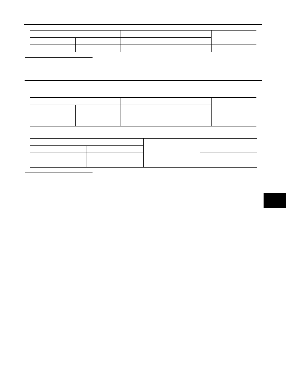
Monitor item
Condition
Value
MIR/SEN RH U-D
Door mirror (passenger side)
Change between
3.4 [V] (close to peak)
0.6 [V] (close to valley)
MIR/SEN RH R-L
Change between
3.4 [V] (close to left edge)
0.6 [V] (close to right edge)
(+)
(–)
Voltage (V)
(Approx.)
Door mirror (passenger side)
Connector
Terminal
D33
23
Ground
5
Automatic drive positioner control unit
Door mirror (passenger side)
Continuity
Connector
Terminal
Connector
Terminal
M52
33
D33
23
Existed
Automatic drive positioner control unit
Ground
Continuity
Connector
Terminal
M52
33
Not existed
MIRROR SENSOR
ADP-107
< DTC/CIRCUIT DIAGNOSIS >
C
D
E
F
G
H
I
K
L
M
A
B
ADP
N
O
P
Is the inspection result normal?
YES
>> GO TO 4.
NO
>> Repair or replace harness.
4.
CHECK DOOR MIRROR (PASSENGER SIDE) SENSOR HARNESS CONTINUITY
1.
Check continuity between automatic drive positioner control unit harness connector and door mirror (pas-
senger side) harness connector.
2.
Check continuity between automatic drive positioner control unit harness connector and ground.
Is the inspection result normal?
YES
>> Replace door mirror sensor. (Built in passenger side door mirror).
NO
>> Repair or replace harness.
Automatic drive positioner control unit
Door mirror (passenger side)
Continuity
Connector
Terminal
Connector
Terminal
M52
41
D33
24
Existed
Automatic drive positioner control unit
Door mirror (passenger side)
Continuity
Connector
Terminal
Connector
Terminal
M51
5
D33
21
Existed
21
22
Automatic drive positioner control unit
Ground
Continuity
Connector
Terminal
M51
5
Not existed
21
Нет комментариевНе стесняйтесь поделиться с нами вашим ценным мнением.
Текст