Infiniti FX35, FX50 (S51). Manual — part 1125
PRECAUTIONS
HA-13
< PRECAUTION >
[VQ35HR]
C
D
E
F
G
H
J
K
L
M
A
B
HA
N
O
P
requirements of SAE J-2210 [HFC-134a (R-134a) recycling equipment], or J-2209 [HFC-134a (R-134a)
recovery equipment]. Ventilate work area before resuming service if accidental system discharge
occurs. Additional health and safety information may be obtained from refrigerant and lubricant
manufacturers.
• Never release refrigerant into the air. Use approved recovery/recycling recharging equipment to cap-
ture the refrigerant each time an air conditioning system is discharged.
• Wear always eye and hand protection (goggles and gloves) when working with any refrigerant or air
conditioning system.
• Never store or heat refrigerant containers above 52
°
C (126
°
F).
• Never heat a refrigerant container with an open flame; Place the bottom of the container in a warm
pail of water if container warming is required.
• Never intentionally drop, puncture, or incinerate refrigerant containers.
• Keep refrigerant away from open flames: poisonous gas is produced if refrigerant burns.
• Refrigerant displaces oxygen, therefore be certain to work in well ventilated areas to prevent suffo-
cation.
• Never pressure test or leakage test HFC-134a (R-134a) service equipment and/or vehicle air condi-
tioning systems with compressed air during repair. Some mixtures of air and HFC-134a (R-134a)
have been shown to be combustible at elevated pressures. These mixtures, if ignited, may cause
injury or property damage. Additional health and safety information may be obtained from refriger-
ant manufacturers.
Refrigerant Connection
INFOID:0000000005249889
A new type refrigerant connection has been introduced to all refrigerant lines except the following location.
• Expansion valve to evaporator
• Refrigerant pressure sensor to liquid tank
ABOUT ONE-TOUCH JOINT
Description
• One-touch joints are pipe joints which do not require tools during piping connection.
• Unlike conventional connection methods using union nuts and flanges, controlling tightening torque at con-
nection point is not necessary.
• Use a disconnector when removing a pipe joint.
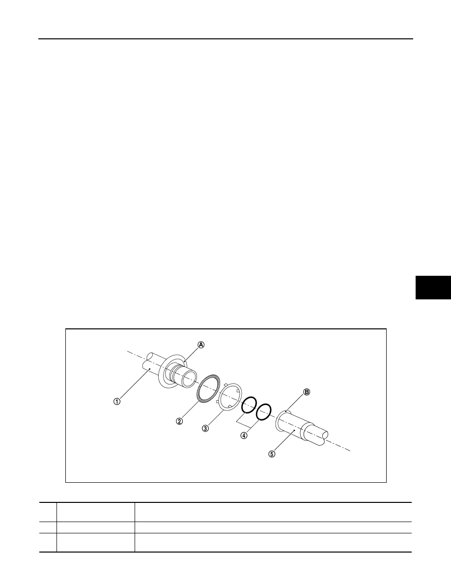
COMPONENT PARTS
FUNCTIONS OF COMPONENT PARTS
1
Pipe (Male-side)
• Retains O-rings.
• Retains garter spring in cage (A).
2
Garter spring
Anchors female-side piping.
3
Indicator ring
When connection is made properly, this is ejected from male-side piping. (This part is no longer nec-
essary after connection.)
RJIA4383J
HA-14
< PRECAUTION >
[VQ35HR]
PRECAUTIONS
NOTE:
• Garter spring cannot be removed from cage of male-side piping.
• Indicator ring remains near piping connection point, however, this is not a malfunction. (This is to check pip-
ing connection during factory assembly.)
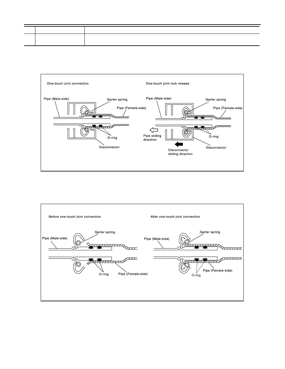
REMOVAL
1.
Clean piping connection point, and set a disconnector.
2.
Slide disconnector in axial direction of piping, and stretch garter spring with tapered point of disconnector.
3.
Slide disconnector farther so that inside diameter of garter spring becomes larger than outside diameter of
female-side piping flare. Then male-side piping can be disconnected.
INSTALLATION
1.
Clean piping connection points, and insert male-side piping into female-side piping.
2.
Push inserted male-side piping harder so that female-side piping flare stretches garter spring.
3.
Garter spring seats on flare if inside diameter of garter spring becomes larger than outside diameter of
female-side piping flare. Then, it fits in between male-side piping cage and female-side piping flare to
anchor piping connection point.
NOTE:
When garter spring seats on flare, and fits in between male-side piping cage and female-side piping flare,
it clicks.
CAUTION:
4
O-ring
Seals connection point. (Not reusable)
5
Pipe (Female-side)
• Seals connection by compressing O-rings.
• Anchors piping connection using flare (B) and garter spring.
SJIA0106E
SJIA0107E
PRECAUTIONS
HA-15
< PRECAUTION >
[VQ35HR]
C
D
E
F
G
H
J
K
L
M
A
B
HA
N
O
P
• Female-side piping connection point is thin and easy to deform. Slowly insert the male-side pip-
ing straight in axial direction.
• Insert piping securely until a click is heard.
• After piping connection is completed, pull male-side piping by hand to make sure that connec-
tion does not come loose.
O-RING AND REFRIGERANT CONNECTION
CAUTION:
The new and former refrigerant connections use different O-ring configurations. Never confuse O-
rings since they are not interchangeable. Refrigerant may leak at the connection if a wrong O-ring is
installed.
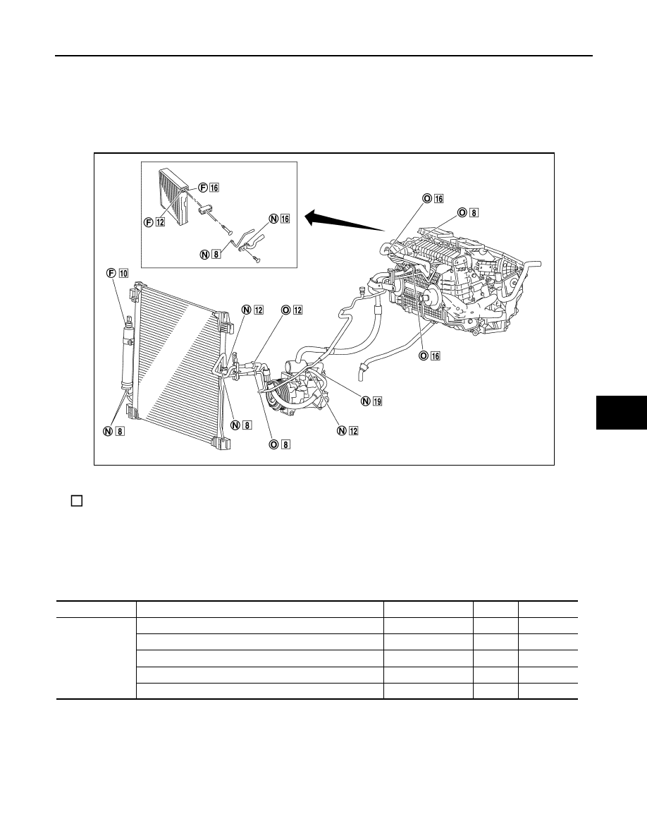
O-Ring Part Numbers and Specifications
F.
Former type refrigerant connection
N.
New type refrigerant connection
O.
One-touch joint
:
O-ring size
JSIIA1280ZZ
Connection type
Piping connection point
Part number
QTY
O-ring size
One-touch joint
Low-pressure pipe 1 to low-pressure pipe 2
92473 N8221
2
16
Low-pressure flexible hose to low-pressure pipe 2
92473 N8221
2
16
High-pressure pipe 1 to high-pressure pipe 2
92471 N8221
2
8
Condenser pipe assembly to high-pressure flexible hose
92472 N8221
2
12
Condenser pipe assembly to high-pressure pipe 1
92471 N8221
2
8
HA-16
< PRECAUTION >
[VQ35HR]
PRECAUTIONS
WARNING:
Check that all refrigerant is discharged into the recycling equipment and the pressure in the system is
less than atmospheric pressure. Then gradually loosen the discharge side hose fitting and remove it.
CAUTION:
Observe the following when replacing or cleaning refrigerant cycle components.
• Store it in the same way at it is when mounted on the car when the compressor is removed. Failure
to do so will cause lubricant to enter the low-pressure chamber.
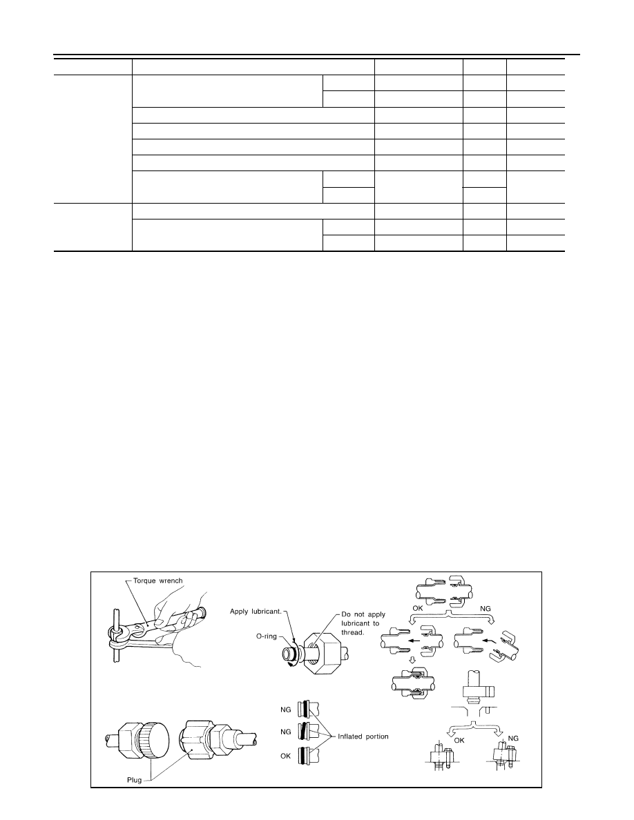
• Use always a torque wrench and a back-up wrench when connecting tubes.
• Plug immediately all openings to prevent entry of dust and moisture after disconnecting tubes.
• Connect the pipes at the final stage of the operation when installing an air conditioner in the vehicle.
Never remove the seal caps of pipes and other components until just before required for connection.
• Allow components stored in cool areas to warm to working area temperature before removing seal
caps. This prevents condensation from forming inside A/C components.
• Remove thoroughly moisture from the refrigeration system before charging the refrigerant.
• Replace always used O-rings.
• Apply lubricant to circle of the O-rings shown in illustration when connecting tube. Be careful not to
apply lubricant to threaded portion.
• O-ring must be closely attached to the groove portion of tube.
• Be careful not to damage O-ring and tube when replacing the O-ring.
• Connect tube until a click can be heard. Then tighten the nut or bolt by hand. Check that the O-ring is
installed to tube correctly.
• Perform leakage test and make sure that there is no leakage from connections after connecting line.
Disconnect that line and replace the O-ring when the refrigerant leaking point is found. Then tighten
connections of seal seat to the specified torque.
New
Condenser to condenser pipe assembly
Inlet
92472 N8210
1
12
Outlet
92471 N8210
1
8
Low-pressure pipe 1 to expansion valve
92473 N8210
1
16
High-pressure pipe 2 to expansion valve
92471 N8210
1
8
Compressor to low-pressure flexible hose
92474 N8210
1
19
Compressor to high-pressure flexible hose
92472 N8210
1
12
Liquid tank to Condenser
Inlet
92471 N8210
1
8
Outlet
1
Former
Refrigerant pressure sensor to liquid tank
J2476 89956
1
10
Expansion valve to evaporator
Inlet
92475 71L00
1
12
Outlet
92475 72L00
1
16
Name
: NISSAN A/C System Oil Type S
Connection type
Piping connection point
Part number
QTY
O-ring size
RHA861F
Нет комментариевНе стесняйтесь поделиться с нами вашим ценным мнением.
Текст