Infiniti FX35, FX50 (S51). Manual — part 751
ECM
EC-545
< ECU DIAGNOSIS INFORMATION >
[VQ35HR]
C
D
E
F
G
H
I
J
K
L
M
A
EC
N
P
O
*1: 1st trip DTC No. is the same as DTC No.
*2: This number is prescribed by SAE J2012/ISO 15031-4.
*3: In Diagnostic Test Mode II (Self-diagnostic results), this number is controlled by NISSAN.
*4: The troubleshooting for this DTC needs CONSULT-III.
*5: When the fail-safe operations for both self-diagnoses occur, the MIL illuminates.
*6: SRT code will not be set if the self-diagnostic result is NG.
*7: When the ECM is in the mode that displays SRT status, MIL may blink. For the details, refer to “How to Display SRT Status”.
*8: When erasing this DTC, always use CONSULT-III or GST.
How to Set SRT Code
INFOID:0000000005237125
To set all SRT codes, self-diagnosis for the items indicated above must be performed one or more times. Each
diagnosis may require a long period of actual driving under various conditions.
WITH CONSULT-III
Perform corresponding DTC Confirmation Procedure one by one based on Performance Priority in the table
on “SRT Item”.
WITHOUT CONSULT-III
The most efficient driving pattern in which SRT codes can be properly set is explained below. The driving pat-
tern should be performed one or more times to set all SRT codes.
P1805
1805
BRAKE SW/CIRCUIT
—
2
—
P2100
2100
ETC MOT PWR-B1
—
1
×
P2101
2101
ETC FNCTN/CIRC-B1
—
1
×
P2103
2103
ETC MOT PWR
—
1
×
P2118
2118
ETC MOT-B1
—
1
×
P2119
2119
ETC ACTR-B1
—
1
×
P2122
2122
APP SEN 1/CIRC
—
1
×
P2123
2123
APP SEN 1/CIRC
—
1
×
P2127
2127
APP SEN 2/CIRC
—
1
×
P2128
2128
APP SEN 2/CIRC
—
1
×
P2132
2132
TP SEN 1/CIRC-B2
—
1
×
P2133
2133
TP SEN 1/CIRC-B2
—
1
×
P2135
2135
TP SENSOR-B1
—
1
×
P2138
2138
APP SENSOR
—
1
×
P2713
2713
PRESS CONTROL SOL D
—
2
×
P2722
2722
PRESS CONTROL SOL E
—
2
×
P2731
2731
PRESS CONTROL SOL F
—
2
×
P2807
2807
PRESS CONTROL SOL G
—
2
×
P2A00
2A00
A/F SENSOR1 (B1)
—
2
×
P2A03
2A03
A/F SENSOR1 (B2)
—
2
×
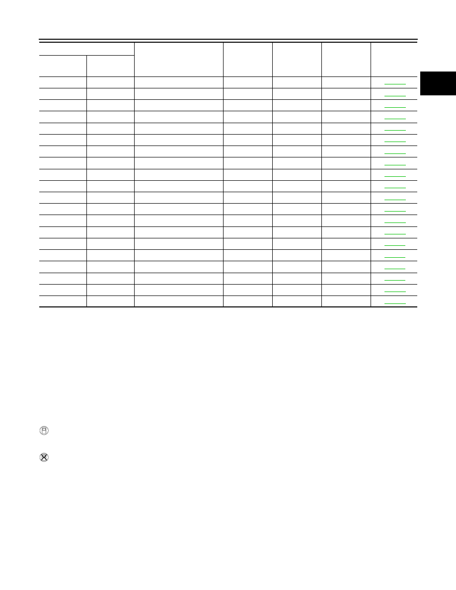
DTC*
1
Items
(CONSULT-III screen terms)
SRT code
Trip
MIL
Reference
page
CONSULT-III
GST*
2
ECM*
3
EC-546
< ECU DIAGNOSIS INFORMATION >
[VQ35HR]
ECM
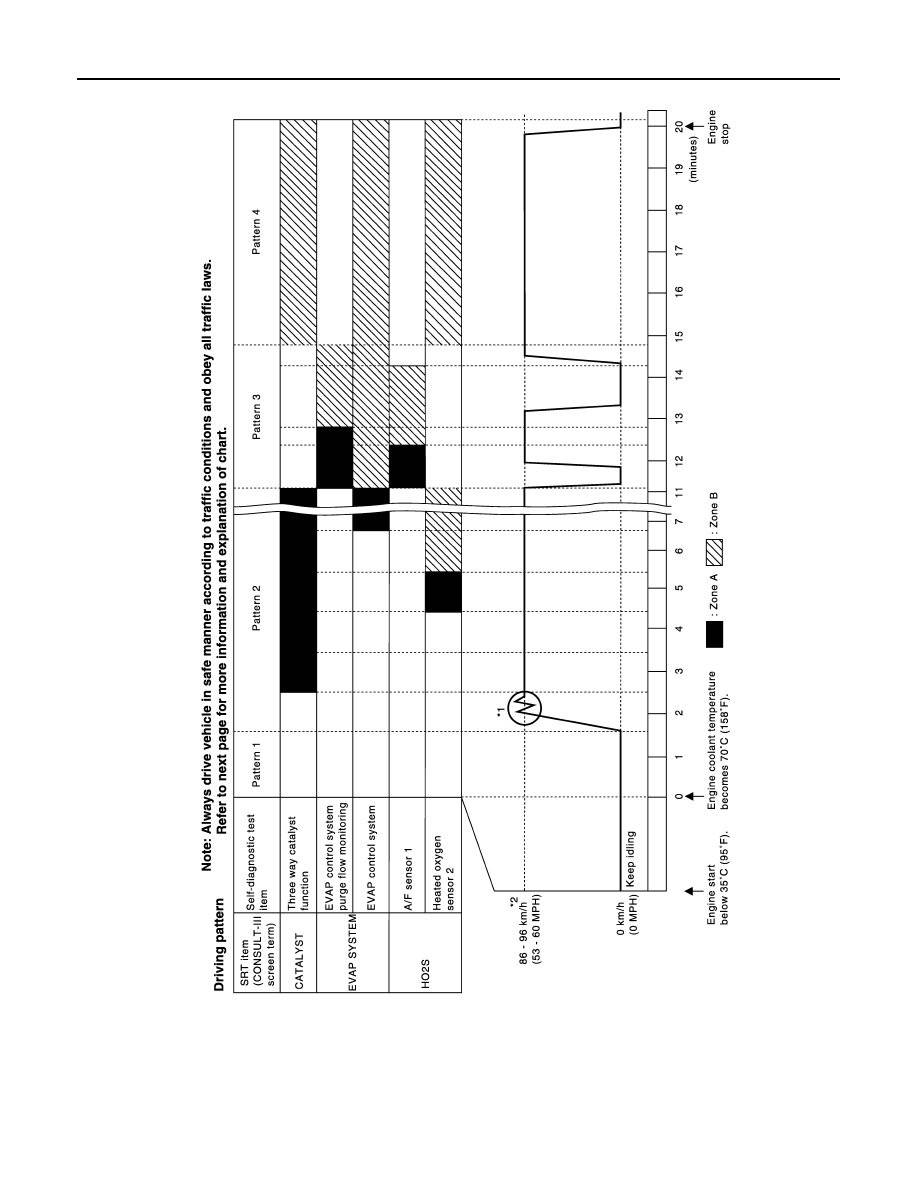
DRIVING PATTERN
• The time required for each diagnosis varies with road surface conditions, weather, altitude, individual driving
habits, etc.
Zone A refers to the range where the time, required for the diagnosis under normal conditions*, is the short-
est.
Zone B refers to the range where the diagnosis can still be performed if the diagnosis is not completed within
zone A.
*: Normal conditions refer to the following:
PBIB3622E
ECM
EC-547
< ECU DIAGNOSIS INFORMATION >
[VQ35HR]
C
D
E
F
G
H
I
J
K
L
M
A
EC
N
P
O
• Sea level
• Flat road
• Ambient air temperature: 20 - 30
°
C (68 - 86
°
F)
• Diagnosis is performed as quickly as possible under normal conditions.
Under different conditions [For example: ambient air temperature other than 20 - 30
°
C (68 - 86
°
F)], diagno-
sis may also be performed.
Pattern 1:
• The engine is started at the engine coolant temperature of
−
10 to 35
°
C (14 to 95
°
F)
(where the voltage between the ECM terminal 71 and ground is 3.0 - 4.3 V).
• The engine must be operated at idle speed until the engine coolant temperature is greater than 70
°
C
(158
°
F) (where the voltage between the ECM terminal 71 and ground is lower than 1.4 V).
• The engine is started at the fuel tank temperature of warmer than 0
°
C (32
°
F) (where the voltage
between the ECM terminal 106 and ground is less than 4.1 V).
Pattern 2:
• When steady-state driving is performed again even after it is interrupted, each diagnosis can be conducted.
In this case, the time required for diagnosis may be extended.
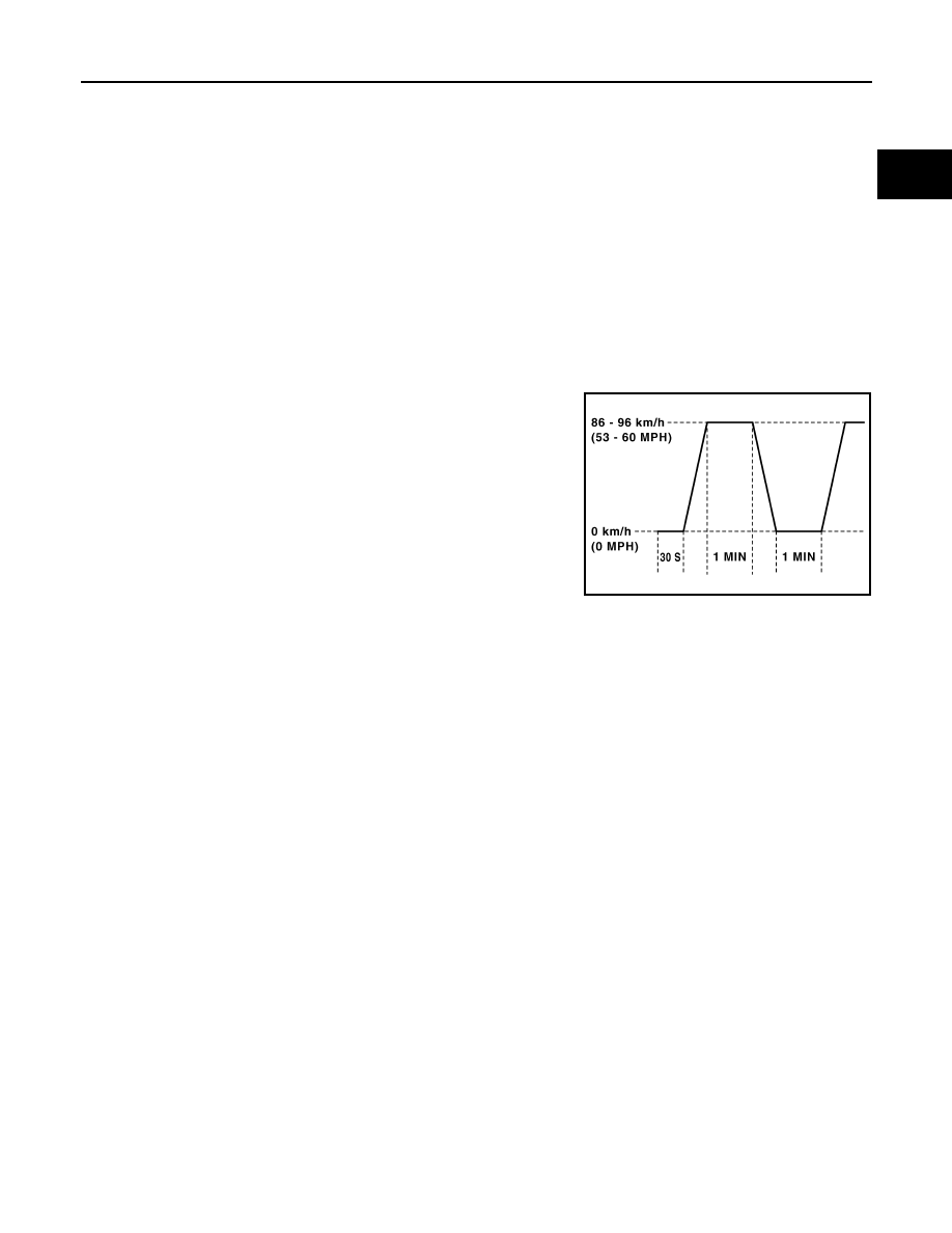
Pattern 3:
• Operate vehicle following the driving pattern shown in the figure.
• Release the accelerator pedal during deceleration of vehicle speed
from 90 km/h (56 MPH) to 0 km/h (0 MPH).
Pattern 4:
• The accelerator pedal must be held very steady during steady-
state driving.
• If the accelerator pedal is moved, the test must be conducted
again.
*1: Depress the accelerator pedal until vehicle speed is 90 km/h (56
MPH), then release the accelerator pedal and keep it released for
more than 10 seconds. Depress the accelerator pedal until vehicle
speed is 90 km/h (56 MPH) again.
*2: Checking the vehicle speed with GST is advised.
Suggested Transmission Gear Position for A/T Models
Set the selector lever position in the D with the overdrive switch turned ON.
Test Value and Test Limit
INFOID:0000000005569658
The following is the information specified in Service $06 of SAE J1979/ISO 15031-5.
The test value is a parameter used to determine whether a system/circuit diagnostic test is OK or NG while
being monitored by the ECM during self-diagnosis. The test limit is a reference value which is specified as the
maximum or minimum value and is compared with the test value being monitored.
These data (test value and test limit) are specified by On Board Monitor ID (OBDMID), Test ID (TID), Unit and
Scaling ID and can be displayed on the GST screen.
The items of the test value and test limit will be displayed with GST screen which items are provided by the
ECM. (eg., if bank 2 is not applied on this vehicle, only the items of bank 1 are displayed)
PBIB2244E

EC-548
< ECU DIAGNOSIS INFORMATION >
[VQ35HR]
ECM
Item
OBD-
MID
Self-diagnostic test item
DTC
Test value and Test
limit
(GST display)
Description
TID
Unit and
Scaling
ID
HO2S
01H
Air fuel ratio (A/F) sensor 1
(Bank 1)
P0131
83H
0BH
Minimum sensor output voltage for test
cycle
P0131
84H
0BH
Maximum sensor output voltage for test
cycle
P0130
85H
0BH
Minimum sensor output voltage for test
cycle
P0130
86H
0BH
Maximum sensor output voltage for test
cycle
P0133
87H
04H
Response rate: Response ratio (Lean to
Rich)
P0133
88H
04H
Response rate: Response ratio (Rich to
Lean)
P2A00
89H
84H
The amount of shift in air fuel ratio
P2A00
8AH
84H
The amount of shift in air fuel ratio
P0130
8BH
0BH
Difference in sensor output voltage
P0133
8CH
83H
Response gain at the limited frequency
P014C
8DH
04H
O2 Sensor Slow Response - Rich to
Lean Bank 1 Sensor 1
P014C
8EH
04H
O2 Sensor Slow Response - Rich to
Lean Bank 1 Sensor 1
P014D
8FH
84H
O2 Sensor Slow Response - Lean to
Rich Bank 1 Sensor 1
P014D
90H
84H
O2 Sensor Slow Response - Lean to
Rich Bank 1 Sensor 1
P015A
91H
01H
O2 Sensor Delayed Response - Rich to
Lean Bank 1 Sensor 1
P015A
92H
01H
O2 Sensor Delayed Response - Rich to
Lean Bank 1 Sensor 1
P015B
93H
01H
O2 Sensor Delayed Response - Lean to
Rich Bank 1 Sensor 1
P015B
94H
01H
O2 Sensor Delayed Response - Lean to
Rich Bank 1 Sensor 1
02H
Heated oxygen sensor 2
(Bank 1)
P0138
07H
0CH
Minimum sensor output voltage for test
cycle
P0137
08H
0CH
Maximum sensor output voltage for test
cycle
P0138
80H
0CH
Sensor output voltage
P0139
81H
0CH
Difference in sensor output voltage
03H
Heated oxygen sensor 3
(Bank 1)
P0143
07H
0CH
Minimum sensor output voltage for test
cycle
P0144
08H
0CH
Maximum sensor output voltage for test
cycle
P0146
80H
0CH
Sensor output voltage
P0145
81H
0CH
Difference in sensor output voltage
Нет комментариевНе стесняйтесь поделиться с нами вашим ценным мнением.
Текст