Infiniti FX35, FX50 (S51). Manual — part 330
CCS-140
< DTC/CIRCUIT DIAGNOSIS >
[ICC (FULL SPEED RANGE)]
POWER SUPPLY AND GROUND CIRCUIT
POWER SUPPLY AND GROUND CIRCUIT
ICC SENSOR INTEGRATED UNIT
ICC SENSOR INTEGRATED UNIT : Diagnosis Procedure
INFOID:0000000005501730
1.
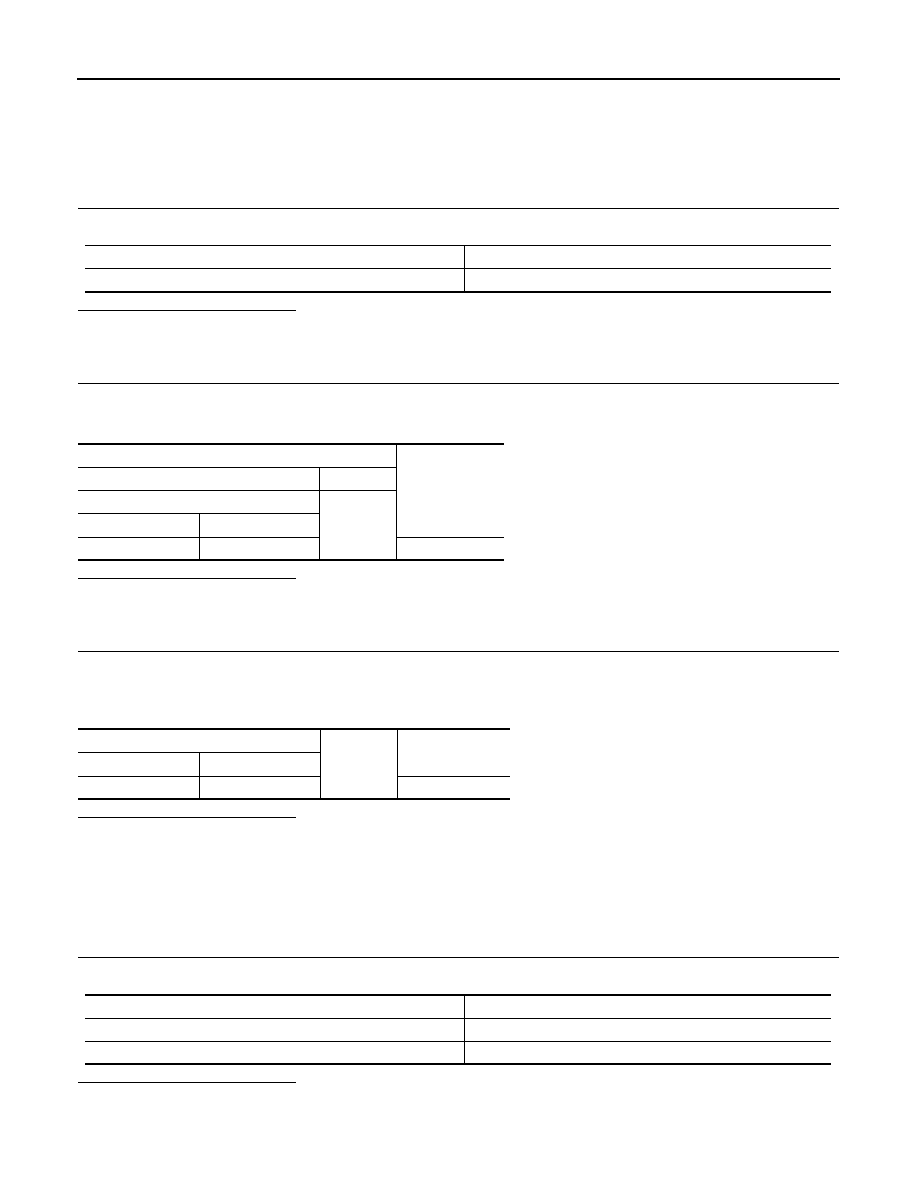
CHECK FUSES
Check if any of the following fuses are blown:
Is the inspection result normal?
YES
>> GO TO 2.
NO
>> Replace the blown fuse after repairing the affected circuit if a fuse is blown.
2.
CHECK ICC SENSOR INTEGRATED UNIT POWER SUPPLY CIRCUIT
1.
Turn the ignition switch ON.
2.
Check voltage between ICC sensor integrated unit harness connector and ground.
Is the inspection result normal?
YES
>> GO TO 3.
NO
>> Repair the ICC sensor integrated unit power supply circuit.
3.
CHECK ICC SENSOR INTEGRATED UNIT GROUND CIRCUIT
1.
Turn the ignition switch OFF.
2.
Disconnect the ICC sensor integrated unit connector.
3.
Check for continuity between ICC sensor integrated unit harness connector and ground.
Is the inspection result normal?
YES
>> INSPECTION END
NO
>> Repair the ICC sensor integrated unit ground circuit.
BRAKE BOOSTER CONTROL UNIT
BRAKE BOOSTER CONTROL UNIT : Diagnosis Procedure
INFOID:0000000005501731
1.
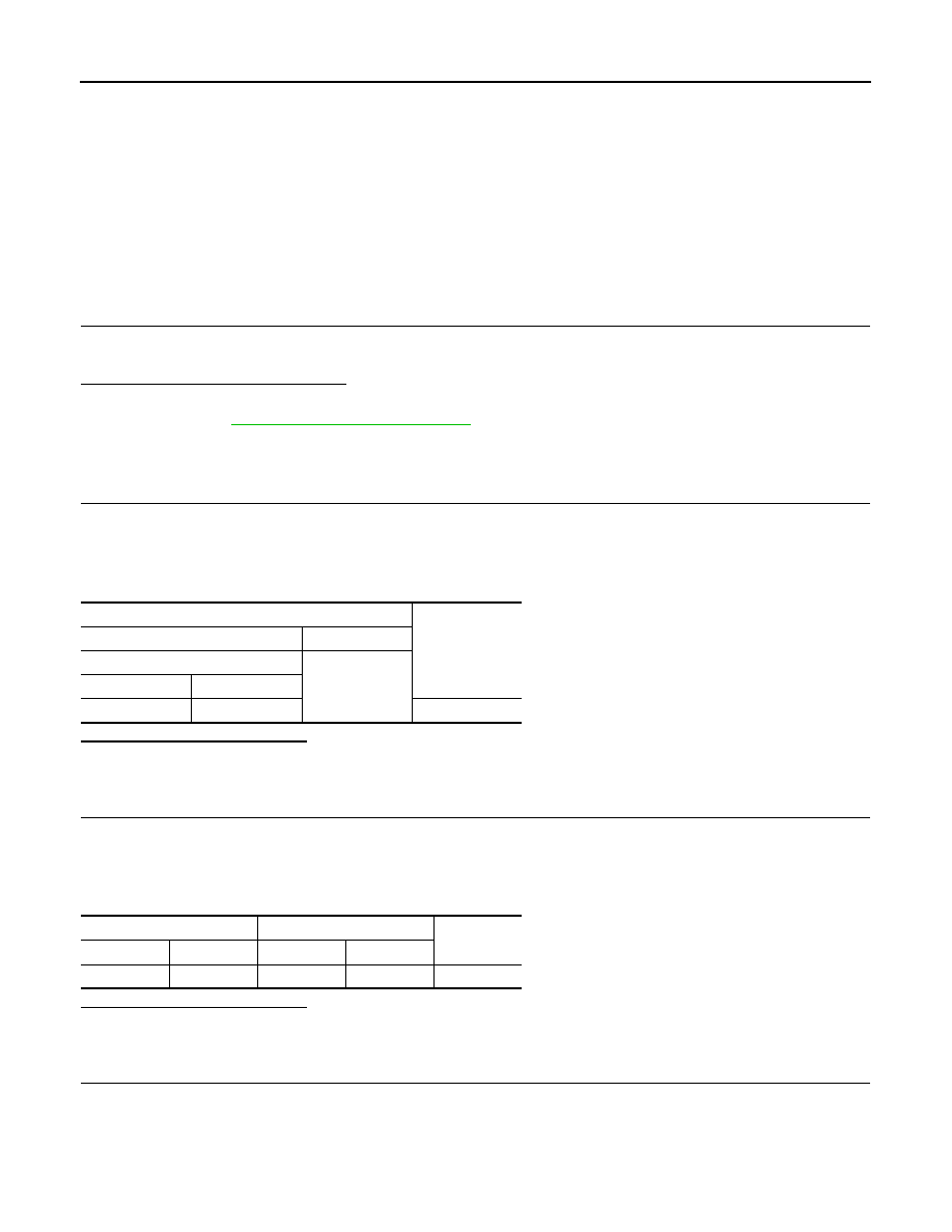
CHECK FUSES
Check if any of the following fuses are blown:
Is the inspection result normal?
YES
>> GO TO 2.
NO
>> Replace the blown fuse after repairing the affected circuit if a fuse is blown.
Signal name
Fuse No.
Ignition power supply
45
Terminal
Voltage
(Approx.)
(+)
(–)
ICC sensor integrated unit
Ground
Connector
Terminal
E67
1
Battery voltage
ICC sensor integrated unit
Ground
Continuity
Connector
Terminal
E67
4
Existed
Signal name
Fuse No.
Battery power supply
33
Ignition power supply
45

CCS
POWER SUPPLY AND GROUND CIRCUIT
CCS-141
< DTC/CIRCUIT DIAGNOSIS >
[ICC (FULL SPEED RANGE)]
C
D
E
F
G
H
I
J
K
L
M
B
N
P
A
2.
CHECK BRAKE BOOSTER CONTROL UNIT POWER SUPPLY CIRCUIT
1.
Turn the ignition switch ON.
2.
Check voltage between brake booster control unit harness connector and ground.
Is the inspection result normal?
YES
>> GO TO 3.
NO
>> Repair the brake booster control unit power supply circuit.
3.
CHECK BRAKE BOOSTER CONTROL UNIT GROUND CIRCUIT
1.
Turn the ignition switch OFF.
2.
Disconnect brake booster control unit connector.
3.
Check for continuity between brake booster control unit harness connector and ground.
Is the inspection result normal?
YES
>> INSPECTION END
NO
>> Repair the brake booster control unit ground circuit.
Terminal
Condition
Voltage
(Approx.)
(+)
(–)
Brake booster control unit
Ground
Ignition
switch
Connector
Terminal
B250
1
OFF
Battery volt-
age
2
B249
33
ON
42
Brake booster control unit
Ground
Continuity
Connector
Terminal
B250
19
Existed
20
B249
46
CCS-142
< DTC/CIRCUIT DIAGNOSIS >
[ICC (FULL SPEED RANGE)]
ICC WARNING CHIME CIRCUIT
ICC WARNING CHIME CIRCUIT
Description
INFOID:0000000005501732
• The ICC sensor integrated unit transmits the buzzer output signal to the brake booster control unit via ITS
communication.
• The brake booster control unit outputs the buzzer output signal to the ICC warning chime.
• A warning chime sounds when the system is canceled or when the vehicle distance from the vehicle ahead
is too close.
Component Function Check
INFOID:0000000005501733
1.
ICC WARNING CHIME OPERATION INSPECTION
1.
Select the active test item “ICC BUZZER” of “ICC” with CONSULT-III.
2.
Check if the ICC warning chime sounds when operating each test item.
Does the ICC warning chime sound?
YES
>> The ICC warning chime circuit is normal.
NO
>> Refer to
CCS-142, "Diagnosis Procedure"
Diagnosis Procedure
INFOID:0000000005501734
1.
CHECK ICC WARNING CHIME POWER SUPPLY CIRCUIT
1.
Turn ignition switch OFF.
2.
Disconnect the ICC warning chime connector.
3.
Turn ignition switch ON.
4.
Check voltage between ICC warning chime harness connector and ground.
Is the inspection result normal?
YES
>> GO TO 2.
NO
>> Repair the harnesses or connectors.
2.
CHECK ICC WARNING CHIME SIGNAL CIRCUIT
1.
Turn ignition switch OFF.
2.
Disconnect brake booster control unit connector.
3.
Check for continuity between the ICC warning chime harness connector and brake booster control unit
harness connector.
Is the inspection result normal?
YES
>> GO TO 3.
NO
>> Repair the harnesses or connectors.
3.
CHECK ICC WARNING CHIME SIGNAL CIRCUIT SHORT
Check for continuity between ICC warning chime harness connector and ground.
Terminals
Voltage
(Approx.)
(+)
(–)
ICC warning chime
Ground
Connector
Terminal
M17
1
Battery voltage
ICC warning chime
Brake booster control unit
Continuity
Connector
Terminal
Connector
Terminal
M17
3
B250
21
Existed
CCS
ICC WARNING CHIME CIRCUIT
CCS-143
< DTC/CIRCUIT DIAGNOSIS >
[ICC (FULL SPEED RANGE)]
C
D
E
F
G
H
I
J
K
L
M
B
N
P
A
Is the inspection result normal?
YES
>> GO TO 4.
NO
>> Repair the harnesses or connectors.
4.
CHECK ICC WARNING CHIME
Check the ICC warning chime. Refer to
CCS-143, "Component Inspection"
.
Is the inspection result normal?
YES
>> Replace the brake booster control unit.
NO
>> Replace the ICC warning chime.
Component Inspection
INFOID:0000000005501735
1.
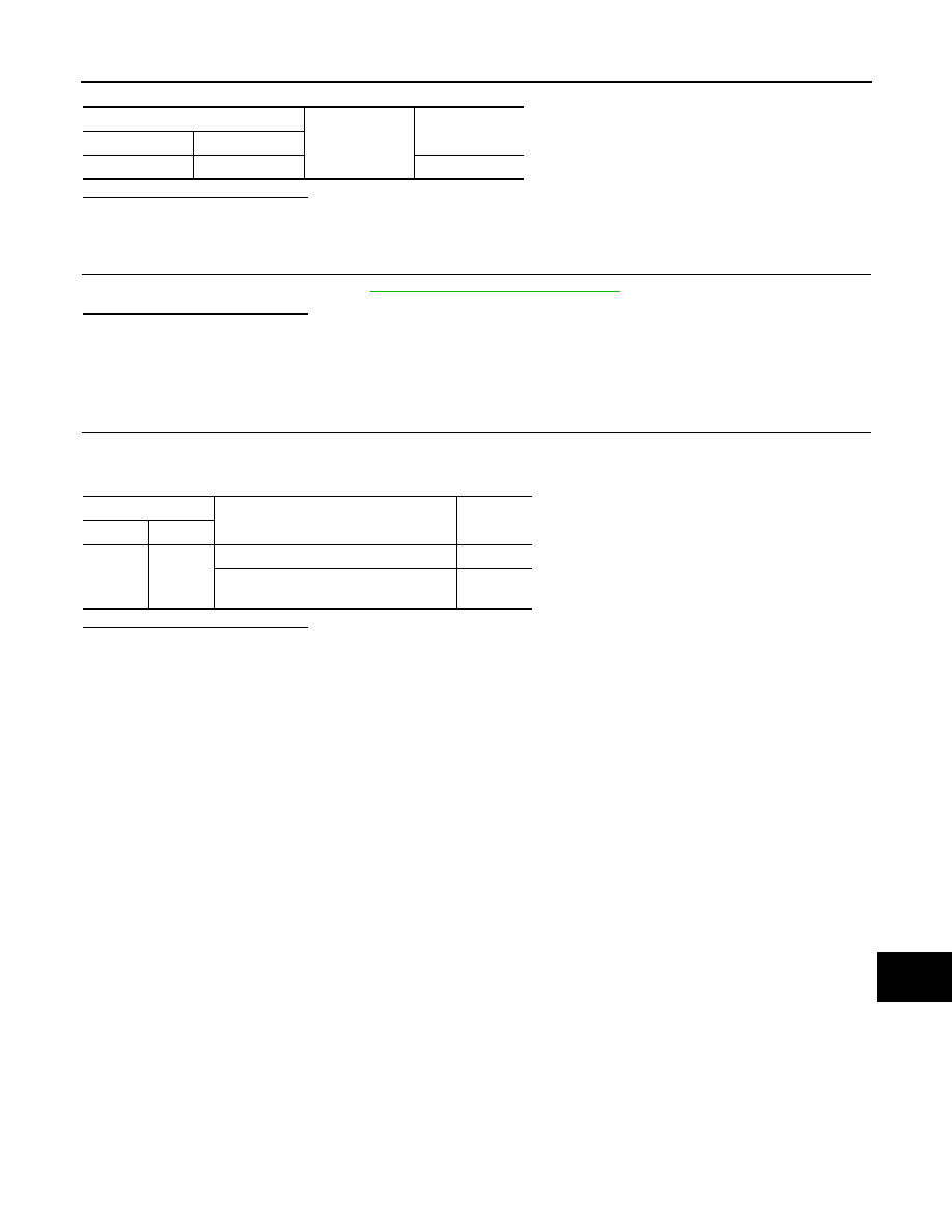
ICC WARNING CHIME INSPECTION
Apply the battery voltage between ICC warning chime terminals, and then check if the ICC warning chime
sounds.
Is the inspection result normal?
YES
>> INSPECTION END
NO
>> Replace the ICC warning chime.
ICC warning chime
Ground
Continuity
Connector
Terminal
M17
3
Not existed
Terminal
Condition
Warning
chime
(+)
(–)
1
3
When the battery voltage is applied
Sounds
When the battery voltage is not applied
Does not
sound
Нет комментариевНе стесняйтесь поделиться с нами вашим ценным мнением.
Текст