Infiniti FX35, FX50 (S51). Manual — part 161
AV
VIDEO DISTRIBUTOR
AV-417
< ECU DIAGNOSIS INFORMATION >
[NAVIGATION (TWIN MONITOR)]
C
D
E
F
G
H
I
J
K
L
M
B
A
O
P
26
(R)
Ground
RGB signal (G: green) for
rear display unit
Output
Ignition
switch
ON
Rear seat remote controller
operation when AUX or
DVD image is displayed on
rear display unit.
27
Ground
Shield
—
—
—
—
28
(B)
Ground
RGB signal (B: blue) for
rear display unit
Output
Ignition
switch
ON
Rear seat remote controller
operation when AUX or
DVD image is displayed on
rear display unit.
29
(R)
Ground
Vertical synchronizing (VP)
signal
Input
Ignition
switch
ON
—
30
(W)
Ground
Horizontal synchronizing
(HP) signal
Input
Ignition
switch
ON
—
31
—
Shield
—
—
—
—
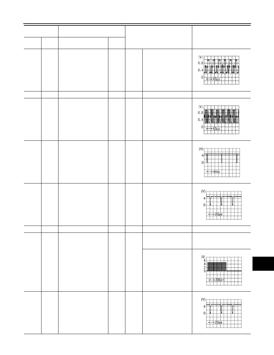
32
(B)
Ground
RGB area (YS) signal
Output
Ignition
switch
ON
When AUX or DVD image
is displayed on rear display
unit.
0 V
Rear seat remote controller
operation when AUX or
DVD image is displayed on
rear display unit.
33
(G)
Ground
Composite synchronizing
signal
Output
Ignition
switch
ON
When AUX or DVD image
is displayed on rear display
unit.
Terminal
(Wire color)
Description
Condition
Reference value
(Approx.)
+
–
Signal name
Input/
Output
JSNIA1030ZZ
JSNIA1031ZZ
SKIB3598E
SKIB0825E
PKIB4948J
SKIB0825E
AV-418
< ECU DIAGNOSIS INFORMATION >
[NAVIGATION (TWIN MONITOR)]
VIDEO DISTRIBUTOR
34
(R)
Ground
Composite image signal
Output
Ignition
switch
ON
When AUX or DVD image
is displayed on rear display
unit.
35
—
Shield
—
—
—
—
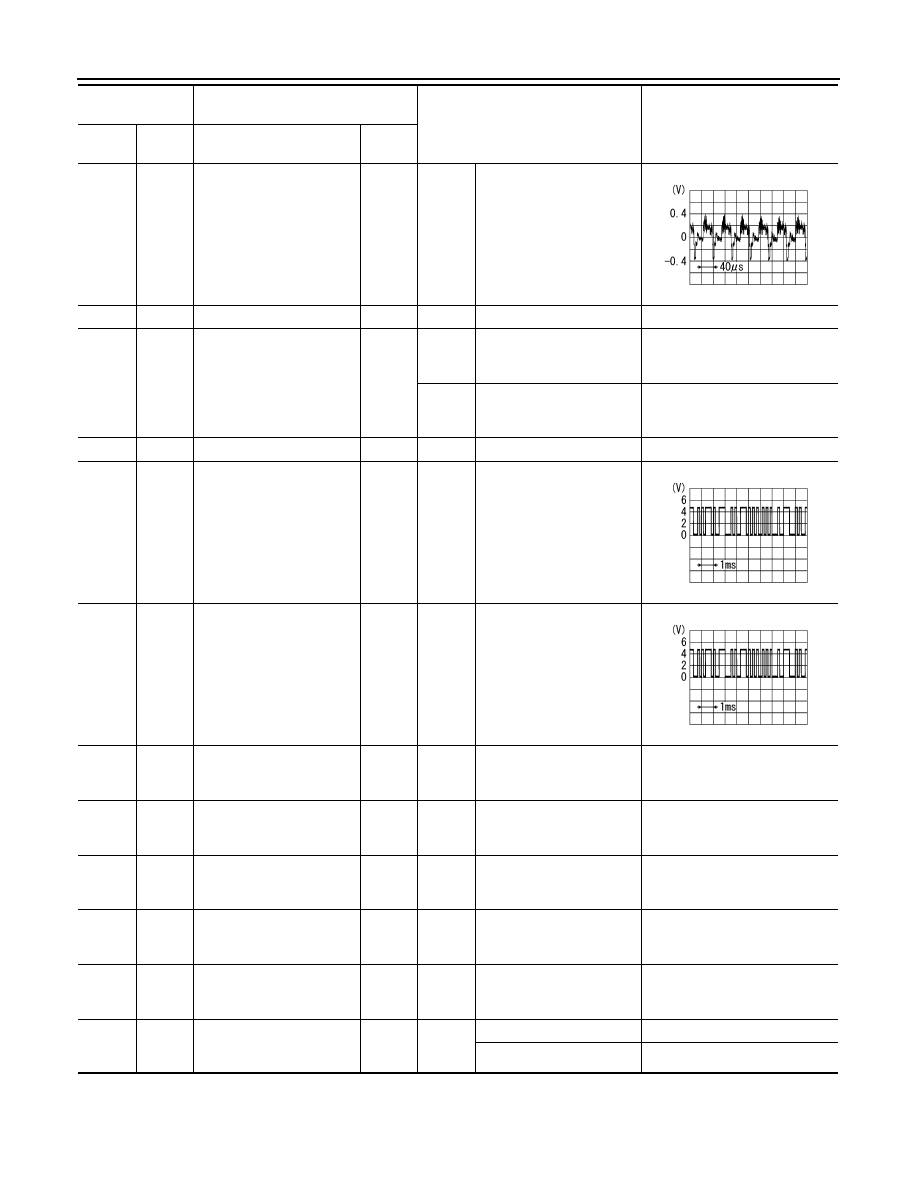
36
(O)
Ground
Ignition signal
Output
Ignition
switch
ON
—
0 V
Ignition
switch
ACC
—
5.0 V
38
—
Shield
—
—
—
—
39
(V)
Ground
Communication signal
(DISP
→
DIST)
Input
Ignition
switch
ON
Rear seat remote controller
operation when AUX or
DVD image is displayed on
rear display unit.
40
(SB)
Ground
Communication signal
(DIST
→
DISP)
Output
Ignition
switch
ON
Rear seat remote controller
operation when AUX or
DVD image is displayed on
rear display unit.
51
(B)
Ground
Ground
—
Ignition
switch
ON
—
0 V
53
(B)
Ground
Ground
—
Ignition
switch
ON
—
0 V
54
(Y)
Ground
Battery power supply
Input
Ignition
switch
OFF
—
Battery voltage
55
(SB)
Ground
ACC power supply
Input
Ignition
switch
ACC
—
Battery voltage
56
(G)
Ground
Ignition signal
Input
Ignition
switch
ON
—
Battery voltage
60
(P)
Ground
Headphone ON signal
Output
Ignition
switch
ON
Headphone mode is ON.
4.0 V
Headphone mode is OFF.
0 V
Terminal
(Wire color)
Description
Condition
Reference value
(Approx.)
+
–
Signal name
Input/
Output
SKIB2251J
PKIB5039J
PKIB5039J
AV
BOSE AMP.
AV-419
< ECU DIAGNOSIS INFORMATION >
[NAVIGATION (TWIN MONITOR)]
C
D
E
F
G
H
I
J
K
L
M
B
A
O
P
BOSE AMP.
Reference Value
INFOID:0000000005474753
TERMINAL LAYOUT
PHYSICAL VALUES
JSNIA0760ZZ
Terminal
(Wire color)
Description
Condition
Reference value
(Approx.)
+
–
Signal name
Input/
Output
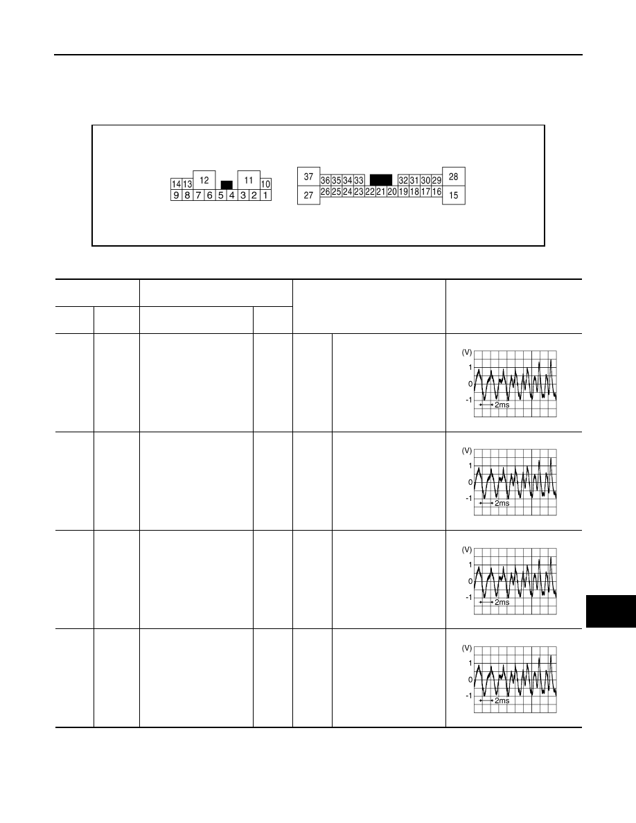
1
(Y)
10
(G)
Sound signal rear door
speaker LH
Output
Ignition
switch
ON
Sound output
2
(SB)
3
(V)
Sound signal rear door
speaker RH
Output
Ignition
switch
ON
Sound output
4
(L)
5
(P)
Sound signal front door
speaker LH
Output
Ignition
switch
ON
Sound output
6
(O)
7
(W)
Sound signal front squawk-
er LH
Output
Ignition
switch
ON
Sound output
SKIB3609E
SKIB3609E
SKIB3609E
SKIB3609E
AV-420
< ECU DIAGNOSIS INFORMATION >
[NAVIGATION (TWIN MONITOR)]
BOSE AMP.
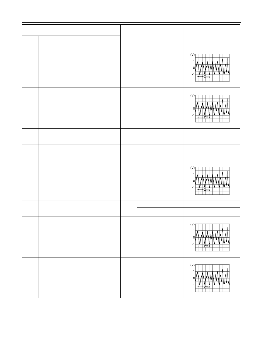
8
(LG)
13
(Y)
Sound signal front door
speaker RH
Output
Ignition
switch
ON
Sound output
9
(G)
14
(R)
Sound signal woofer and
rear squawker
Output
Ignition
switch
ON
Sound output
11
(GR)
Ground
Battery power supply
Input
Ignition
switch
ON
—
Battery voltage
12
(B)
Ground
Ground
—
Ignition
switch
ON
—
0 V
15
(Y)
28
(G)
Sound signal center speak-
er
Output
Ignition
switch
ON
Sound output
17
(O)
Ground
Mode change signal
Input
Ignition
switch
ON
Driver's Audio Stage ON
0 V
Driver's Audio Stage OFF
8.5 V
18
(P)
32
(L)
Sound signal front LH
Input
Ignition
switch
ON
Sound output
19
(R)
20
(G)
Sound signal front RH
Input
Ignition
switch
ON
Sound output
Terminal
(Wire color)
Description
Condition
Reference value
(Approx.)
+
–
Signal name
Input/
Output
SKIB3609E
SKIB3609E
SKIB3609E
SKIB3609E
SKIB3609E
Нет комментариевНе стесняйтесь поделиться с нами вашим ценным мнением.
Текст