Infiniti FX35, FX50 (S51). Manual — part 1943
ROAD WHEEL TIRE ASSEMBLY
WT-75
< REMOVAL AND INSTALLATION >
C
D
F
G
H
I
J
K
L
M
A
B
WT
N
O
P
2.
Check wheels for deformation, clacks and other damage. If deformed, remove wheel and check wheel
runout.
a.
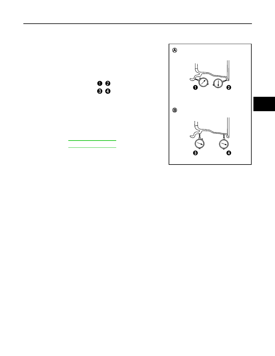
Remove tire from steel wheel and mount wheel on a tire balance machine.
b.
Set two dial indicators as shown in the illustration.
c.
Set each dial indicator to “0”.
d.
Rotate wheel and check dial indicators at several points around
the circumference of the wheel.
e.
Calculate runout at each point as shown below.
f.
Select maximum positive runout value and the maximum nega-
tive value. Add the two values to determine total runout.
CAUTION:
In case a positive or negative value is not available, use the
maximum value (negative or positive) for total runout.
g.
If the total runout value exceeds limit, replace steel wheel.
Lateral runout limit (A):
(
+
)/2
Radial runout limit (B):
(
+
)/2
Limit
A:
Refer to
B:
Refer to
SEIA0738E
WT-76
< REMOVAL AND INSTALLATION >
TPMS CONTROL UNIT
TPMS CONTROL UNIT
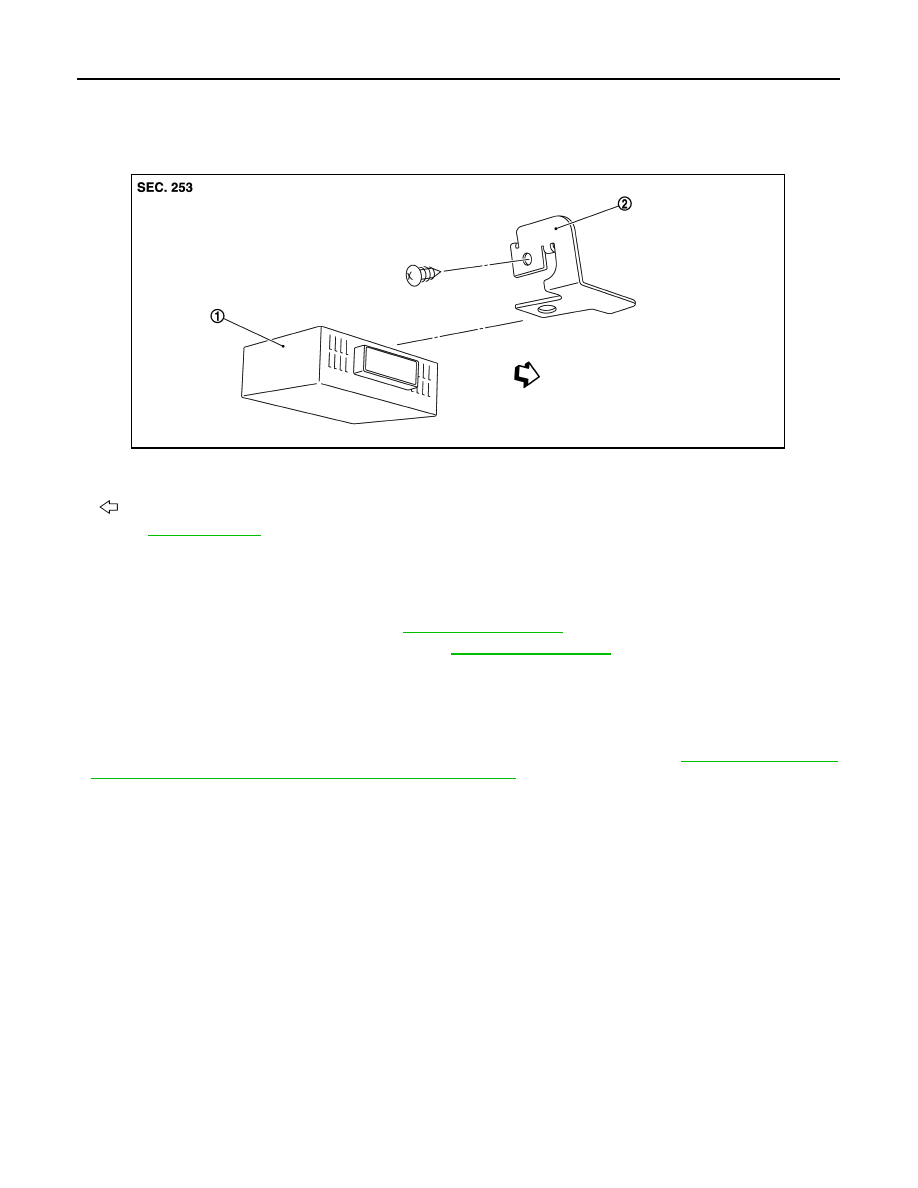
Exploded View
INFOID:0000000005243137
Removal and Installation
INFOID:0000000005243138
REMOVAL
1.
Remove the glove box assembly. Refer to
2.
Remove the instrument lower panel RH. Refer to
3.
Disconnect low tire pressure warning control unit connector.
4.
Remove the low tire pressure warning control unit control unit.
INSTALLATION
Install in the reverse order of removal.
• Perform ID registration after replacing low tire pressure warning control unit. Refer to
TION PROCEDURE : Transmitter ID Registration Procedure"
1.
Low tire pressure warning control unit 2.
Bracket
:Vehicle front
Refer to
for symbols in the figure.
JSEIA0013ZZ
TRANSMITTER
WT-77
< REMOVAL AND INSTALLATION >
C
D
F
G
H
I
J
K
L
M
A
B
WT
N
O
P
TRANSMITTER
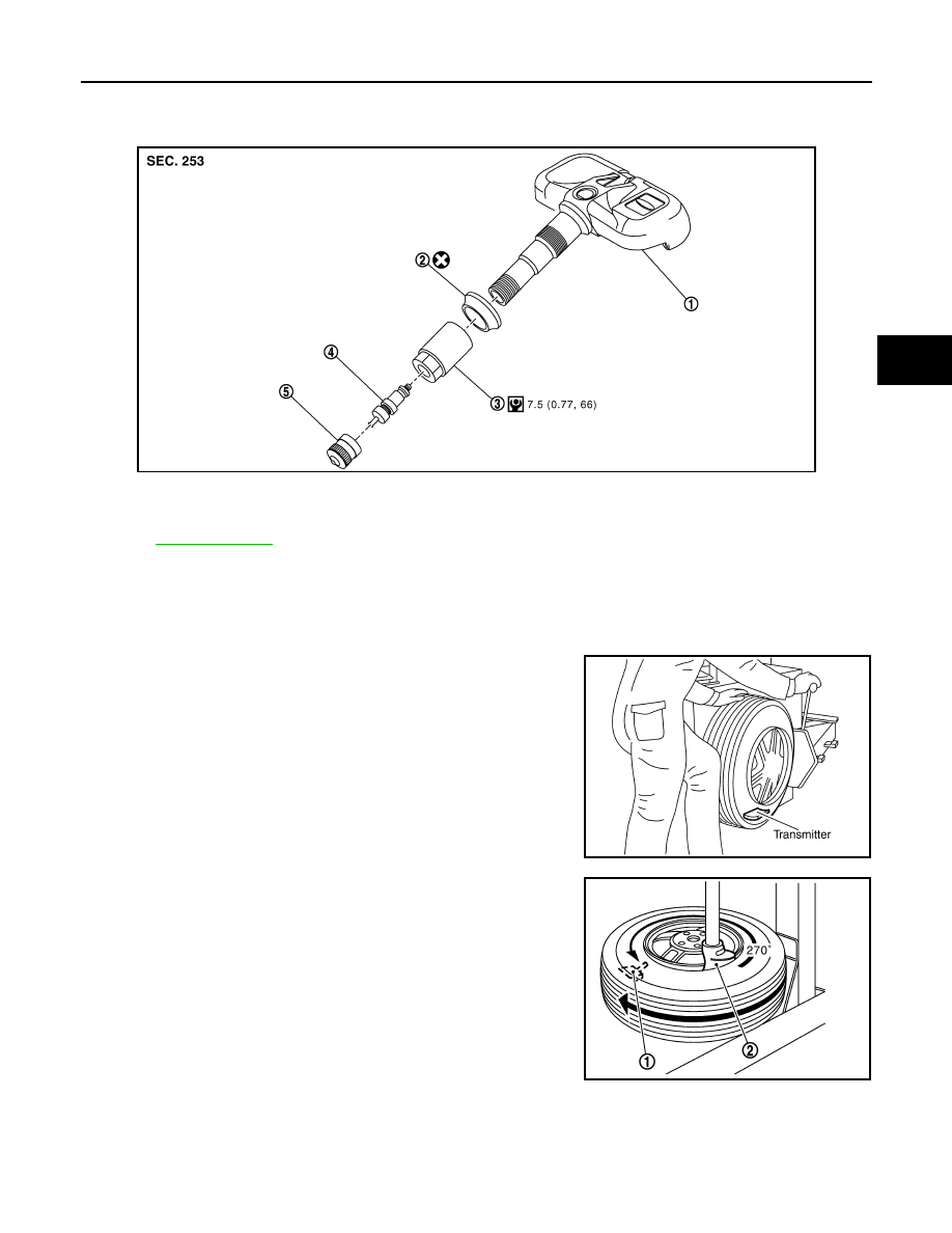
Exploded View
INFOID:0000000005243139
Removal and Installation
INFOID:0000000005243140
REMOVAL
1.
Deflate tire. Unscrew transmitter retaining nut and allow transmitter to fall into tire.
2.
Gently bounce tire so that transmitter falls to bottom of tire.
Place on tire changing machine and break both tire beads
ensuring that the transmitter remains at the bottom of the tire.
3.
Turn tire so that valve hole is at bottom and bounce so that
transmitter (1) is near valve hole. Carefully lift tire onto turntable
and position valve hole (and transmitter) 270 degree from
mounting/dismounting head (2).
4.
Lubricate tire well and remove first side of the tire. Reach inside
the tire and remove the transmitter.
INSTALLATION
JPEIC0006GB
1.
Transmitter
2.
Grommet seal
3.
Valve nut
4.
Valve core
5.
Cap
Refer to
for symbols in figure.
SEIA0047E
JPEIC0014GB
WT-78
< REMOVAL AND INSTALLATION >
TRANSMITTER
1.
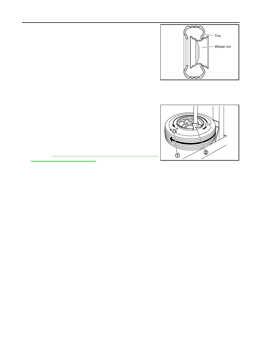
Put first side of tire onto rim.
2.
Mount transmitter on rim and tighten nut.
CAUTION:
Speed for tightening nut should be less than 10 rpm.
3.
Place wheel on turntable of tire machine. Ensure that transmitter
(1) is 270 degree from mounting head (2) when second side of
tire is fitted.
NOTE:
Do not touch transmitter at mounting head.
4.
Lubricate tire well and fit second side of tire as normal. Ensure
that tire does not rotate relative to rim.
5.
Inflate tire and fit to appropriate wheel position.
6.
Perform the transmitter wake-up after replacing transmitter.
Refer to
WT-6, "TRANSMITTER WAKE UP OPERATION :
Transmitter Wake-up Procedure"
SEIA0049E
JPEIC0014GB
Нет комментариевНе стесняйтесь поделиться с нами вашим ценным мнением.
Текст