Infiniti FX35, FX50 (S51). Manual — part 214

BCS
U0415 VEHICLE SPEED SIG
BCS-37
< DTC/CIRCUIT DIAGNOSIS >
C
D
E
F
G
H
I
J
K
L
B
A
O
P
N
U0415 VEHICLE SPEED SIG
Description
INFOID:0000000005249331
U0415 is displayed if any unusual condition is present in the reception status of the vehicle speed signal from
the ABS actuator and electric unit (control unit).
DTC Logic
INFOID:0000000005249332
DTC DETECTION LOGIC
DTC CONFIRMATION PROCEDURE
1.
DTC CONFIRMATION
1.
Erase the DTC.
2.
Turn ignition switch OFF.
3.
Perform the “Self Diagnostic Result” of CONSULT-III, when passed 2 seconds or more after the ignition
switch is turned ON.
Is any DTC detected?
YES
>> Refer to
NO
>> INSPECTION END
Diagnosis Procedure
INFOID:0000000005249333
1.
ABS ACTUATOR AND ELECTRIC UNIT (CONTROL UNIT) SELF-DIAG RESULTS
Perform “Self-Diagnostic Result” of ABS actuator and electric unit (control unit) with CONSULT-III. Refer to
BRC-44, "CONSULT-III Function"
Is any DTC detected?
YES
>> Repair or replace the malfunctioning part.
NO
>> Replace BCM. Refer to
.
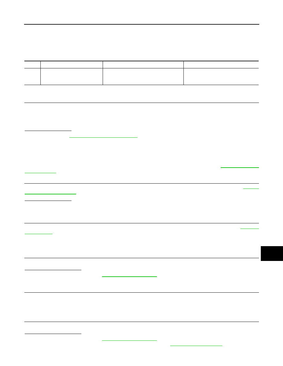
DTC
CONSULT-III display
description
DTC Detection Condition
Probable cause
U0415
VEHICLE SPEED
When the vehicle speed signal received from
the ABS actuator and electric unit (control
unit) remains abnormal for 2 seconds or more.
• ABS actuator and electric unit (control unit)
• BCM

BCS-38
< DTC/CIRCUIT DIAGNOSIS >
B2562 LOW VOLTAGE
B2562 LOW VOLTAGE
DTC Logic
INFOID:0000000005249334
DTC DETECTION LOGIC
DTC CONFIRMATION PROCEDURE
1.
DTC CONFIRMATION
1.
Erase DTC.
2.
Turn ignition switch OFF.
3.
Perform the “Self Diagnostic Result” of CONSULT-III, when passed 120 seconds or more after the ignition
switch is turned ON.
Is any DTC detected?
YES
>> Refer to
.
NO
>> INSPECTION END
Diagnosis Procedure
INFOID:0000000005249335
1.
CHECK POWER SUPPLY CIRCUIT
Check BCM power supply circuit. Refer to
Is the circuit normal?
YES
>> Replace BCM. Refer to
NO
>> Repair the malfunctioning part.
DTC
CONSULT-III display
description
DTC Detection Condition
Possible cause
B2562
LOW VOLTAGE
When the power supply voltage to BCM remains less
than 8.8 V for 120 seconds or more
Harness or connector (power supply
circuit)
BCS
B26E7 TPMS CAN COMM
BCS-39
< DTC/CIRCUIT DIAGNOSIS >
C
D
E
F
G
H
I
J
K
L
B
A
O
P
N
B26E7 TPMS CAN COMM
DTC Logic
INFOID:0000000005249336
DTC DETECTION LOGIC
DTC CONFIRMATION PROCEDURE
1.
DTC CONFIRMATION
1.
Erase the DTC.
2.
Turn ignition switch OFF.
3.
Perform the “Self Diagnostic Result” of CONSULT-III, when passed 2 seconds or more after the ignition
switch is turned ON.
Is any DTC detected?
YES
>> Refer to
NO
>> INSPECTION END
Diagnosis Procedure
INFOID:0000000005249337
NOTE:
If DTC “B26E7” detected along with DTC “U1000”, first diagnose the DTC “U1000”. Refer to
1.
LOW TIRE PRESSURE WARNING CONTROL UNIT SELF DIAGNOSTIC RESULT
Perform “Self Diagnostic Result” of low tire pressure warning control unit with CONSULT-III. Refer to
.
Is any DTC detected?
YES
>> GO TO 2.
NO
>> GO TO 4.
2.
LOW TIRE PRESSURE WARNING CONTROL UNIT DIAGNOSIS
Perform low tire pressure warning control unit component diagnosis of detected DTC. Refer to
>> GO TO 3.
3.
BCM SELF DIAGNOSTIC RESULT
Erase DTC of BCM, and perform “Self Diagnostic Result” again.
Is DTC “B26E7” detected?
YES
>> Replace BCM. Refer to
.
NO
>> INSPECTION END
4.
REPLACE LOW TIRE PRESSURE WARNING CONTROL UNIT TEMPORARILY
Remove low tire pressure warning control unit, and install normal low tire pressure warning control unit.
>> GO TO 5.
5.
BCM SELF-DIAGNOSTIC RESULT
Erase DTC of BCM, and perform “Self Diagnostic Result” again.
Is DTC “B26E7” detected?
YES
>> Replace BCM. Refer to
.
NO
>> Replace low tire pressure warning control unit. Refer to
.
DTC
CONSULT-III display description
DTC Detection Condition
Probable cause
B26E7
TPMS CAN COMM
When ignition switch is ON, BCM cannot re-
ceived CAN communication signal from low
tire pressure warning control unit.
• CAN communication system
• Low tire pressure warning control unit
• BCM
BCS-40
< DTC/CIRCUIT DIAGNOSIS >
POWER SUPPLY AND GROUND CIRCUIT
POWER SUPPLY AND GROUND CIRCUIT
Diagnosis Procedure
INFOID:0000000005249338
1.
CHECK FUSE AND FUSIBLE LINK
Check that the following fuse and fusible link are not blown.
Is the fuse fusing?
YES
>> Replace the blown fuse or fusible link after repairing the affected circuit if a fuse or fusible link is
blown.
NO
>> GO TO 2.
2.
CHECK POWER SUPPLY CIRCUIT
1.
Turn ignition switch OFF.
2.
Disconnect BCM connectors.
3.
Check voltage between BCM harness connector and ground.
Is the measurement value normal?
YES
>> GO TO 3.
NO
>> Repair harness or connector.
3.
CHECK GROUND CIRCUIT
Check continuity between BCM harness connector and ground.
Does continuity exist?
YES
>> INSPECTION END
NO
>> Repair harness or connector.
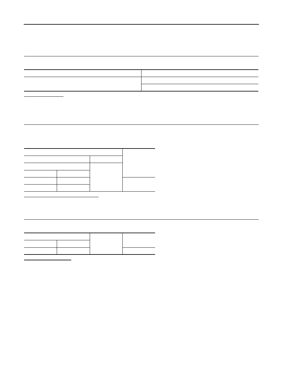
Signal name
Fuse and fusible link No.
Battery power supply
L
10
Terminals
Voltage
(Approx.)
(+)
(
−
)
BCM
Ground
Connector
Terminal
M118
1
Battery voltage
M119
11
BCM
Ground
Continuity
Connector
Terminal
M119
13
Existed
Нет комментариевНе стесняйтесь поделиться с нами вашим ценным мнением.
Текст