Infiniti FX35, FX50 (S51). Manual — part 242

SERVICE DATA AND SPECIFICATIONS (SDS)
BR-65
< SERVICE DATA AND SPECIFICATIONS (SDS)
C
D
E
G
H
I
J
K
L
M
A
B
BR
N
O
P
SERVICE DATA AND SPECIFICATIONS (SDS)
SERVICE DATA AND SPECIFICATIONS (SDS)
General Specifications
INFOID:0000000005234223
FRONT 2 PISTON, REAR 1 PISTON TYPE
Unit: mm (in)
FRONT 4 PISTON, REAR 2 PISTON TYPE
Unit: mm (in)
Brake Pedal
INFOID:0000000005234224
Unit: mm (in)
Front brake
Cylinder bore diameter
45.0 (1.772)
×
2
Pad length
×
width
×
thickness
130
×
50.0
×
11.0 (5.12
×
1.969
×
0.433)
Rotor outer diameter
×
thickness
320
×
34.0 (12.60
×
1.339)
Rear brake
Cylinder bore diameter
42.86 (1.687)
Pad length
×
width
×
thickness
83.0
×
33.0
×
8.5 (3.268
×
1.299
×
0.335)
Rotor outer diameter
×
thickness
308
×
16.0 (12.13
×
0.630)
Master cylinder
Cylinder bore diameter
25.4 (1)
Control valve
Valve type
Electric brake force distribution
Brake booster
Diaphragm diameter
Primary: 230 (9.06)
Secondary: 205 (8.07)
Recommended brake fluid
Refer to
MA-12, "Fluids and Lubricants"
Front brake
Cylinder bore diameter
41.3 (1.626)
×
2 + 44.45 (1.750)
×
2
Pad length
×
width
×
thickness
123.2
×
55.0
×
11.0 (4.85
×
2.165
×
0.433)
Rotor outer diameter
×
thickness
355
×
32.0 (13.98
×
1.260)
Rear brake
Cylinder bore diameter
41.3 (1.626)
×
2
Pad length
×
width
×
thickness
95.8
×
41.5
×
9.5 (3.772
×
1.634
×
0.374)
Rotor outer diameter
×
thickness
350
×
20.0 (13.78
×
0.787)
Master cylinder
Cylinder bore diameter
25.4 (1)
Control valve
Valve type
Electric brake force distribution
Brake booster
Diaphragm diameter
Primary: 230 (9.06)
Secondary: 205 (8.07)
Recommended brake fluid
Refer to
MA-12, "Fluids and Lubricants"
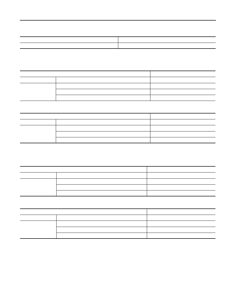
Item
Standard
Brake pedal height
Without DCA
171.5 – 181.5 (6.75 – 7.15)
With DCA
185.4 – 195.4 (7.30 – 7.69)
Clearance between the stop lamp switch and ASCD brake switch threaded end and the
stopper rubber
0.74 – 1.96 (0.0291 – 0.0772)
Brake pedal play
3.0 – 11.0 (0.118 – 0.433)
Depressed brake pedal height
[Depressing 490 N (50 kg, 110 lb) while turning the engine ON]
Without DCA
114.0 (4.49) or more
With DCA
120.8 (4.76) or more
BR-66
< SERVICE DATA AND SPECIFICATIONS (SDS)
SERVICE DATA AND SPECIFICATIONS (SDS)
Brake Booster
INFOID:0000000005234225
Unit: mm (in)
Front Disc Brake
INFOID:0000000005234226
2 PISTON TYPE
Unit: mm (in)
4 PISTON TYPE
Unit: mm (in)
Rear Disc Brake
INFOID:0000000005234227
1 PISTON TYPE
Unit: mm (in)
2 PISTON TYPE
Unit: mm (in)
Item
Standard
Input rod length
125 (4.92)
Item
Limit
Brake pad
Wear thickness
2.0 (0.079)
Disc rotor
Wear thickness
32.0 (1.260)
Thickness variation (measured at 8 positions)
0.015 (0.0006)
Runout (with it attached to the vehicle)
0.035 (0.0014)
Item
Limit
Brake pad
Wear thickness
2.0 (0.079)
Disc rotor
Wear thickness
30.0 (1.181)
Thickness variation (measured at 8 positions)
0.015 (0.0006)
Runout (with it attached to the vehicle)
0.035 (0.0014)
Item
Limit
Brake pad
Wear thickness
2.0 (0.079)
Disc rotor
Wear thickness
14.0 (0.551)
Thickness variation (measured at 8 positions)
0.015 (0.0006)
Runout (with it attached to the vehicle)
0.055 (0.0022)
Item
Limit
Brake pad
Wear thickness
2.0 (0.079)
Disc rotor
Wear thickness
18.0 (0.709)
Thickness variation (measured at 8 positions)
0.015 (0.0006)
Runout (with it attached to the vehicle)
0.055 (0.0022)
BRC-1
BRAKES
C
D
E
G
H
I
J
K
L
M
SECTION
BRC
A
B
BRC
N
O
P
CONTENTS
BRAKE CONTROL SYSTEM
VDC/TCS/ABS
BASIC INSPECTION . . . . . . . . .
DIAGNOSIS AND REPAIR WORK FLOW . . .
Work Flow . . . . . . . . . . . . . . . .....
Diagnostic Work Sheet . . . . . . . . . . . ..
INSPECTION AND ADJUSTMENT . . . . . .
ADDITIONAL SERVICE WHEN REPLACING
CONTROL UNIT . . . . . . . . . . . . . . ..
ADDITIONAL SERVICE WHEN REPLACING
CONTROL UNIT : Description . . . . . . . . ..
ADDITIONAL SERVICE WHEN REPLACING
CONTROL UNIT : Special Repair Requirement . ...
ADJUSTMENT OF STEERING ANGLE SENSOR
NEUTRAL POSITION . . . . . . . . . . . . ..
ADJUSTMENT OF STEERING ANGLE SENSOR
NEUTRAL POSITION : Description . . . . . . ..
SYSTEM DESCRIPTION . . . . . . . .
VDC . . . . . . . . . . . . . . . . .
System Diagram . . . . . . . . . . . . . ..
System Description . . . . . . . . . . . . .
Component Parts Location . . . . . . . . . ..
Component Description . . . . . . . . . . ...
TCS . . . . . . . . . . . . . . . . . .
System Diagram . . . . . . . . . . . . . ..
System Description . . . . . . . . . . . . .
Component Parts Location . . . . . . . . . ..
Component Description . . . . . . . . . . ...
ABS . . . . . . . . . . . . . . . . .
System Diagram . . . . . . . . . . . . . ..
System Description . . . . . . . . . . . . .
Component Parts Location . . . . . . . . . ..
Component Description . . . . . . . . . . ...
EBD . . . . . . . . . . . . . . . . ...
System Diagram . . . . . . . . . . . . . ..
System Description . . . . . . . . . . . . ..
Component Parts Location . . . . . . . . . ..
Component Description . . . . . . . . . . ...
DIAGNOSIS SYSTEM [ABS ACTUATOR
AND ELECTRIC UNIT (CONTROL UNIT)] . ...
CONSULT-III Function . . . . . . . . . . .
DTC/CIRCUIT DIAGNOSIS . . . . . . .
C1101, C1102, C1103, C1104 WHEEL SEN-
SOR . . . . . . . . . . . . . . . . ...
Description . . . . . . . . . . . . . . . ...
DTC Logic . . . . . . . . . . . . . . . .
Diagnosis Procedure . . . . . . . . . . . ...
Special Repair Requirement . . . . . . . . .
C1105, C1106, C1107, C1108 WHEEL SEN-
SOR . . . . . . . . . . . . . . . . ...
Description . . . . . . . . . . . . . . . ...
DTC Logic . . . . . . . . . . . . . . . .
Diagnosis Procedure . . . . . . . . . . . ...
Special Repair Requirement . . . . . . . . .
C1109 POWER AND GROUND SYSTEM . .
Description . . . . . . . . . . . . . . . ...
DTC Logic . . . . . . . . . . . . . . . .
Diagnosis Procedure . . . . . . . . . . . ...
Special Repair Requirement . . . . . . . . .
C1110, C1153, C1170 ABS ACTUATOR AND
ELECTRIC UNIT (CONTROL UNIT) . . . . .
DTC Logic . . . . . . . . . . . . . . . .
Diagnosis Procedure . . . . . . . . . . . ...
BRC-2
C1111 ABS MOTOR, MOTOR RELAY SYS-
TEM . . . . . . . . . . . . . . . . .
Description . . . . . . . . . . . . . . . ..
DTC Logic . . . . . . . . . . . . . . . ...
Diagnosis Procedure . . . . . . . . . . . ..
Special Repair Requirement . . . . . . . . ...
C1114 ACTUATOR RELAY SYSTEM . . . ...
Description . . . . . . . . . . . . . . . ..
DTC Logic . . . . . . . . . . . . . . . ...
Diagnosis Procedure . . . . . . . . . . . ..
Special Repair Requirement . . . . . . . . ...
C1115 WHEEL SENSOR . . . . . . . . ...
Description . . . . . . . . . . . . . . . ..
DTC Logic . . . . . . . . . . . . . . . ...
Diagnosis Procedure . . . . . . . . . . . ..
Special Repair Requirement . . . . . . . . ...
C1116 STOP LAMP SWITCH . . . . . . .
Description . . . . . . . . . . . . . . . ..
DTC Logic . . . . . . . . . . . . . . . ...
Diagnosis Procedure . . . . . . . . . . . ..
Component Inspection . . . . . . . . . . ....
Special Repair Requirement . . . . . . . . ...
C1120, C1122, C1124, C1126 IN ABS SOL . .
Description . . . . . . . . . . . . . . . ..
DTC Logic . . . . . . . . . . . . . . . ...
Diagnosis Procedure . . . . . . . . . . . ..
Special Repair Requirement . . . . . . . . ...
C1121, C1123, C1125, C1127 OUT ABS SOL ...
Description . . . . . . . . . . . . . . . ..
DTC Logic . . . . . . . . . . . . . . . ...
Diagnosis Procedure . . . . . . . . . . . ..
Special Repair Requirement . . . . . . . . ...
C1130 ENGINE SIGNAL . . . . . . . . ...
Description . . . . . . . . . . . . . . . ..
DTC Logic . . . . . . . . . . . . . . . ...
Diagnosis Procedure . . . . . . . . . . . ..
Special Repair Requirement . . . . . . . . ...
C1137 RAS CIRCUIT . . . . . . . . . . .
Description . . . . . . . . . . . . . . . ..
DTC Logic . . . . . . . . . . . . . . . ...
Diagnosis Procedure . . . . . . . . . . . ..
Special Repair Requirement . . . . . . . . ...
C1142 PRESS SENSOR . . . . . . . . ...
Description . . . . . . . . . . . . . . . ..
DTC Logic . . . . . . . . . . . . . . . ...
Diagnosis Procedure . . . . . . . . . . . ..
Special Repair Requirement . . . . . . . . ...
C1143 STEERING ANGLE SENSOR . . . .
Description . . . . . . . . . . . . . . . ..
DTC Logic . . . . . . . . . . . . . . . ...
Diagnosis Procedure . . . . . . . . . . . ..
Special Repair Requirement . . . . . . . . ...
C1144 STEERING ANGLE SENSOR . . . ...
DTC Logic . . . . . . . . . . . . . . . ...
Diagnosis Procedure . . . . . . . . . . . ...
Special Repair Requirement . . . . . . . . ...
C1145, C1146 YAW RATE/SIDE G SENSOR ...
Description . . . . . . . . . . . . . . . ..
DTC Logic . . . . . . . . . . . . . . . ...
Diagnosis Procedure . . . . . . . . . . . ...
Special Repair Requirement . . . . . . . . ...
C1147, C1148, C1149, C1150 USV/HSV LINE ...
Description . . . . . . . . . . . . . . . ..
DTC Logic . . . . . . . . . . . . . . . ...
Diagnosis Procedure . . . . . . . . . . . ...
Special Repair Requirement . . . . . . . . ...
C1154 TRANSMISSION RANGE SWITCH . ...
Description . . . . . . . . . . . . . . . ..
DTC Logic . . . . . . . . . . . . . . . ...
Diagnosis Procedure . . . . . . . . . . . ...
Special Repair Requirement . . . . . . . . ...
C1155 BRAKE FLUID LEVEL SWITCH . . ...
Description . . . . . . . . . . . . . . . ..
DTC Logic . . . . . . . . . . . . . . . ...
Diagnosis Procedure . . . . . . . . . . . ...
Component Inspection . . . . . . . . . . .
Special Repair Requirement . . . . . . . . ...
C1156 STEERING ANGLE SENSOR (CAN) .
Description . . . . . . . . . . . . . . . ..
DTC Logic . . . . . . . . . . . . . . . ...
Diagnosis Procedure . . . . . . . . . . . ...
Special Repair Requirement . . . . . . . . ...
C1185 ICC UNIT . . . . . . . . . . . .
Description . . . . . . . . . . . . . . . ..
DTC Logic . . . . . . . . . . . . . . . ...
Diagnosis Procedure . . . . . . . . . . . ...
Special Repair Requirement . . . . . . . . ...
C1197 VACUUM SENSOR . . . . . . . .
Description . . . . . . . . . . . . . . . ..
DTC Logic . . . . . . . . . . . . . . . ...
Diagnosis Procedure . . . . . . . . . . . ...
Special Repair Requirement . . . . . . . . ...
C1198 VACUUM SENSOR . . . . . . . .
Description . . . . . . . . . . . . . . . ..
DTC Logic . . . . . . . . . . . . . . . ...
Diagnosis Procedure . . . . . . . . . . . ...
Special Repair Requirement . . . . . . . . ...
C1199 VACUUM SENSOR . . . . . . . .
Description . . . . . . . . . . . . . . . ..
DTC Logic . . . . . . . . . . . . . . . ...
Diagnosis Procedure . . . . . . . . . . . ...
Special Repair Requirement . . . . . . . . ...
Нет комментариевНе стесняйтесь поделиться с нами вашим ценным мнением.
Текст