Infiniti FX35, FX50 (S51). Manual — part 1323
LAN-234
< DTC/CIRCUIT DIAGNOSIS >
[CAN SYSTEM (TYPE 6)]
APA BRANCH LINE CIRCUIT
APA BRANCH LINE CIRCUIT
Diagnosis Procedure
INFOID:0000000005577098
1.
CHECK CONNECTOR
1.
Turn the ignition switch OFF.
2.
Disconnect the battery cable from the negative terminal.
3.
Check the terminals and connectors of the accelerator pedal actuator for damage, bend and loose con-
nection (unit side and connector side).
Is the inspection result normal?
YES
>> GO TO 2.
NO
>> Repair the terminal and connector.
2.
CHECK HARNESS FOR OPEN CIRCUIT
1.
Disconnect the connector of accelerator pedal actuator.
2.
Check the resistance between the accelerator pedal actuator harness connector terminals.
Is the measurement value within the specification?
YES
>> GO TO 3.
NO
>> Repair the accelerator pedal actuator branch line.
3.
CHECK POWER SUPPLY AND GROUND CIRCUIT
Check the power supply and the ground circuit of the accelerator pedal actuator. Refer to
ERATOR PEDAL ACTUATOR : Diagnosis Procedure"
Is the inspection result normal?
YES (Present error)>>Replace the accelerator pedal actuator. Refer to
CONTROL ASSIST SYSTEM : Exploded View"
.
YES (Past error)>>Error was detected in the accelerator pedal actuator branch line.
NO
>> Repair the power supply and the ground circuit.
Accelerator pedal actuator harness connector
Resistance (
Ω
)
Connector No.
Terminal No.
E115
5
3
Approx. 54 – 66

LAN
BCU BRANCH LINE CIRCUIT
LAN-235
< DTC/CIRCUIT DIAGNOSIS >
[CAN SYSTEM (TYPE 6)]
C
D
E
F
G
H
I
J
K
L
B
A
O
P
N
BCU BRANCH LINE CIRCUIT
Diagnosis Procedure
INFOID:0000000005577099
1.
CHECK CONNECTOR
1.
Turn the ignition switch OFF.
2.
Disconnect the battery cable from the negative terminal.
3.
Check the following terminals and connectors for damage, bend and loose connection (unit side and con-
nector side).
-
Brake booster control unit
-
Harness connector B201
-
Harness connector M117
-
Harness connector M6
-
Harness connector E106
Is the inspection result normal?
YES
>> GO TO 2.
NO
>> Repair the terminal and connector.
2.
CHECK HARNESS FOR OPEN CIRCUIT
1.
Disconnect the connector of brake booster control unit.
2.
Check the resistance between the brake booster control unit harness connector terminals.
Is the measurement value within the specification?
YES
>> GO TO 3.
NO
>> Repair or replace (if shield line is open) the brake booster control unit branch line.
3.
CHECK POWER SUPPLY AND GROUND CIRCUIT
Check the power supply and the ground circuit of the brake booster control unit. Refer to
BOOSTER CONTROL UNIT : Diagnosis Procedure"
.
Is the inspection result normal?
YES (Present error)>>Replace the brake booster control unit. Refer to
.
YES (Past error)>>Error was detected in the brake booster control unit branch line.
NO
>> Repair the power supply and the ground circuit.
Brake booster control unit harness connector
Resistance (
Ω
)
Connector No.
Terminal No.
B250
14
5
Approx. 108 – 132
LAN-236
< DTC/CIRCUIT DIAGNOSIS >
[CAN SYSTEM (TYPE 6)]
CAN COMMUNICATION CIRCUIT 1
CAN COMMUNICATION CIRCUIT 1
Diagnosis Procedure
INFOID:0000000005577101
1.
CONNECTOR INSPECTION
1.
Turn the ignition switch OFF.
2.
Disconnect the battery cable from the negative terminal.
3.
Disconnect all the unit connectors on CAN communication circuit 1.
4.
Check terminals and connectors for damage, bend and loose connection.
Is the inspection result normal?
YES
>> GO TO 2.
NO
>> Repair the terminal and connector.
2.
CHECK HARNESS CONTINUITY (SHORT CIRCUIT)
Check the continuity between the data link connector terminals.
Is the inspection result normal?
YES
>> GO TO 3.
NO
>> Check the harness and repair the root cause.
3.
CHECK HARNESS CONTINUITY (SHORT CIRCUIT)
Check the continuity between the data link connector and the ground.
Is the inspection result normal?
YES
>> GO TO 4.
NO
>> Check the harness and repair the root cause.
4.
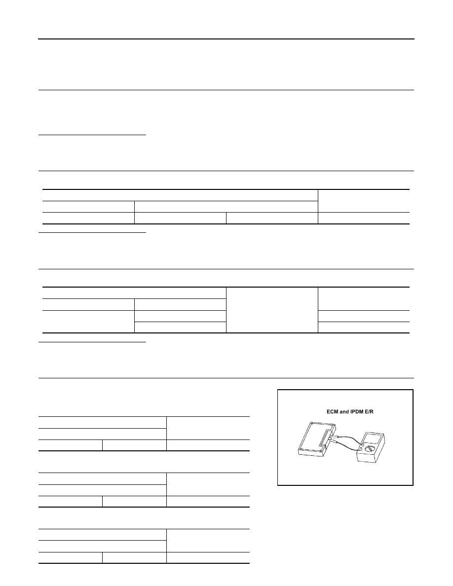
CHECK ECM AND IPDM E/R TERMINATION CIRCUIT
1.
Remove the ECM and the IPDM E/R.
2.
Check the resistance between the ECM terminals.
-
VQ engine models
-
VK engine models
3.
Check the resistance between the IPDM E/R terminals.
Data link connector
Continuity
Connector No.
Terminal No.
M24
6
14
Not existed
Data link connector
Ground
Continuity
Connector No.
Terminal No.
M24
6
Not existed
14
Not existed
ECM
Resistance (
Ω
)
Terminal No.
114
113
Approx. 108 – 132
ECM
Resistance (
Ω
)
Terminal No.
105
101
Approx. 108 – 132
IPDM E/R
Resistance (
Ω
)
Terminal No.
40
39
Approx. 108 – 132
LKIA0037E

LAN
CAN COMMUNICATION CIRCUIT 1
LAN-237
< DTC/CIRCUIT DIAGNOSIS >
[CAN SYSTEM (TYPE 6)]
C
D
E
F
G
H
I
J
K
L
B
A
O
P
N
Is the measurement value within the specification?
YES
>> GO TO 5.
NO
>> Replace the ECM and/or the IPDM E/R.
5.
CHECK SYMPTOM
Connect all the connectors. Check if the symptoms described in the “Symptom (Results from interview with
customer)” are reproduced.
Inspection result
Reproduced>>GO TO 6.
Non-reproduced>>Start the diagnosis again. Follow the trouble diagnosis procedure when past error is
detected.
6.
CHECK UNIT REPRODUCTION
Perform the reproduction test as per the following procedure for each unit.
1.
Turn the ignition switch OFF.
2.
Disconnect the battery cable from the negative terminal.
3.
Disconnect one of the unit connectors of CAN communication circuit 1.
NOTE:
ECM and IPDM E/R have a termination circuit. Check other units first.
4.
Connect the battery cable to the negative terminal. Check if the symptoms described in the “Symptom
(Results from interview with customer)” are reproduced.
NOTE:
Although unit-related error symptoms occur, do not confuse them with other symptoms.
Inspection result
Reproduced>>Connect the connector. Check other units as per the above procedure.
Non-reproduced>>Replace the unit whose connector was disconnected.
Нет комментариевНе стесняйтесь поделиться с нами вашим ценным мнением.
Текст