Infiniti FX35, FX50 (S51). Manual — part 929
EM-16
< PERIODIC MAINTENANCE >
[VQ35HR]
DRIVE BELT
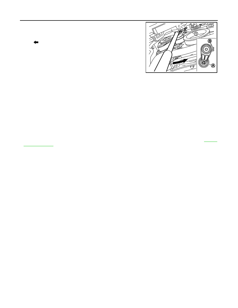
2.
While securely holding the square hole (A) in pulley center of
auto tensioner (1) with a spinner handle, move spinner handle in
the direction of arrow (loosening direction of drive belt).
CAUTION:
Never place hand in a location where pinching may occur if
the holding tool accidentally comes off.
3.
Under the above condition, insert a metallic bar of approximately
6 mm (0.24 in) in diameter [hexagonal wrench (C) shown as
example in the figure] through the holding boss (B) to lock auto-
tensioner pulley arm.
4.
Remove drive belt.
INSTALLATION
Note the following item, and install in the reverse order of removal.
CAUTION:
• Check drive belt is securely installed around all pulleys.
• Check drive belt is correctly engaged with the pulley groove.
• Check for engine oil and engine coolant are not adhered drive belt and pulley groove.
Inspection
INFOID:0000000005245116
INSPECTION AFTER INSTALLATION
• Turn crankshaft pulley clockwise several times to equalize tension between each pulley, and then confirm
tension of drive belt at indicator (notch on fixed side) is within the possible use range. Refer to
: Loosening direction of drive belt
JPBIA0003ZZ
AIR CLEANER FILTER
EM-17
< PERIODIC MAINTENANCE >
[VQ35HR]
C
D
E
F
G
H
I
J
K
L
M
A
EM
N
P
O
AIR CLEANER FILTER
Removal and Installation
INFOID:0000000005245117
REMOVAL
1.
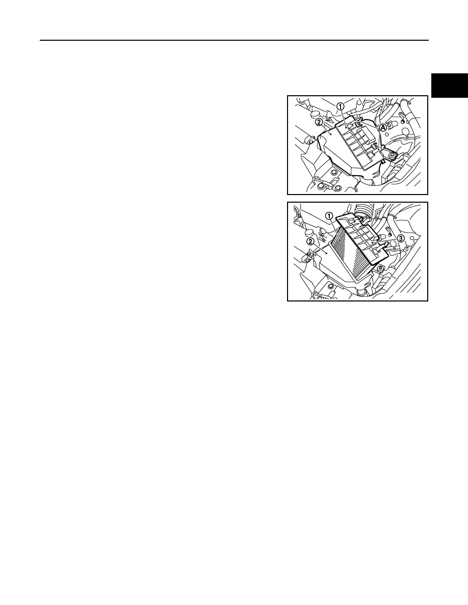
Unhook clips (A).
2.
Remove holder (3) from air cleaner case (2), and then remove
air cleaner filter (1) from holder.
INSTALLATION
Note the following item, and install in the reverse order of removal.
• Install the air cleaner filter by aligning the seal with the notch of air cleaner case.
1
: Holder
2
: Air cleaner case
JPBIA1597ZZ
JPBIA1598ZZ
EM-18
< PERIODIC MAINTENANCE >
[VQ35HR]
SPARK PLUG
SPARK PLUG
Exploded View
INFOID:0000000005245118
Removal and Installation
INFOID:0000000005245119
REMOVAL
1.
Remove engine cover with power tool. Refer to
.
2.
Remove air duct. Refer to
3.
Remove electric throttle control actuator. Refer to
.
4.
Remove ignition coil. Refer to
EM-50, "Removal and Installation"
.
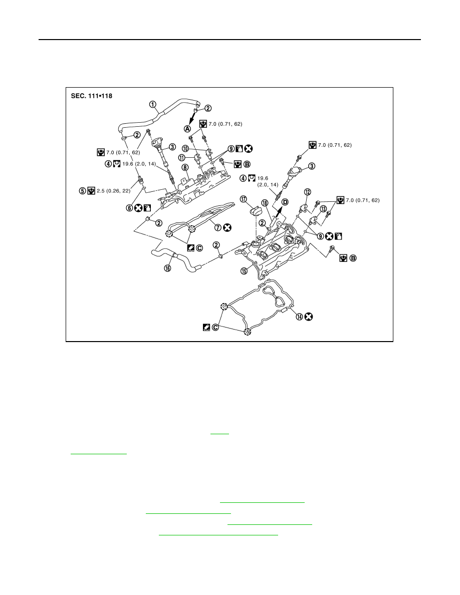
1.
PCV hose
2.
Clamp
3.
Ignition coil
4.
Spark plug
5.
PCV valve
6.
O-ring
7.
Rocker cover gasket (bank 1)
8.
Rocker cover (bank 1)
9.
O-ring
10.
Camshaft position sensor (PHASE)
(bank 1)
11.
Exhaust valve timing control position
sensor (bank 1)
12.
Camshaft position sensor (PHASE)
(bank 2)
13.
Exhaust valve timing control position
sensor (bank 2)
14.
Rocker cover gasket (bank 2)
15. Rocker cover (bank 2)
16.
PCV hose
17.
Oil filler cap
18. PCV hose
A.
To intake manifold collector
B.
Refer to
C.
Camshaft bracket side
D.
To air duct
Refer to
for symbols in the figure.
JPBIA1622GB
SPARK PLUG
EM-19
< PERIODIC MAINTENANCE >
[VQ35HR]
C
D
E
F
G
H
I
J
K
L
M
A
EM
N
P
O
5.
Remove spark plug with a spark plug wrench (commercial ser-
vice tool).
INSTALLATION
Installation is the reverse order of removal.
Inspection
INFOID:0000000005245120
INSPECTION AFTER REMOVAL
Use the standard type spark plug for normal condition.
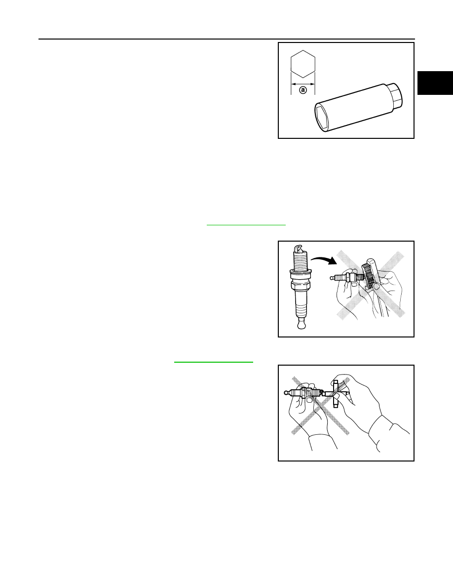
CAUTION:
• Never drop or impact spark plug.
• Never use a wire brush for cleaning.
• If plug tip is covered with carbon, spark plug cleaner may be
used.
• Measure spark plug gap. When it exceeds the limit, replace spark plug even if it is within the speci-
fied replacement mileage. Refer to
• Spark plug gap adjustment is not required between replace-
ment intervals.
a
: 14 mm (0.55 in)
JPBIA0030ZZ
Spark plug (Standard type)
: Refer to
Cleaner air pressure:
Less than 588 kPa (6 kg/cm
2
, 85
psi)
Cleaning time:
Less than 20 seconds
SMA773C
JPBIA0031ZZ
Нет комментариевНе стесняйтесь поделиться с нами вашим ценным мнением.
Текст