Infiniti FX35, FX50 (S51). Manual — part 854

P0550 PSP SENSOR
EC-957
< DTC/CIRCUIT DIAGNOSIS >
[VK50VE]
C
D
E
F
G
H
I
J
K
L
M
A
EC
N
P
O
P0550 PSP SENSOR
Description
INFOID:0000000005237425
Power steering pressure (PSP) sensor is installed to the power steering high-pressure tube and detects a
power steering load.
This sensor is a potentiometer which transforms the power steering load into output voltage, and emits the
voltage signal to the ECM. The ECM controls the electric throttle control actuator and adjusts the throttle valve
opening angle to increase the engine speed and adjusts the idle speed for the increased load.
DTC Logic
INFOID:0000000005237426
DTC DETECTION LOGIC
NOTE:
If DTC P0550 is displayed with DTC P0643, first perform the trouble diagnosis for DTC P0643. Refer to
DTC CONFIRMATION PROCEDURE
1.
PRECONDITIONING
If DTC Confirmation Procedure has been previously conducted, always perform the following procedure
before conducting the next test.
1.
Turn ignition switch OFF and wait at least 10 seconds.
2.
Turn ignition switch ON.
3.
Turn ignition switch OFF and wait at least 10 seconds.
>> GO TO 2.
2.
PERFORM DTC CONFIRMATION PROCEDURE
1.
Start engine and let it idle for at least 5 seconds.
2.
Check 1st trip DTC.
Is 1st trip DTC detected?
YES
>> Go to
NO
>> INSPECTION END
Diagnosis Procedure
INFOID:0000000005237427
1.
CHECK GROUND CONNECTION
1.
Turn ignition switch OFF.
2.
Check ground connection M95. Refer to Ground Inspection in
Is the inspection result normal?
YES
>> GO TO 2.
NO
>> Repair or replace ground connection.
2.
CHECK POWER STEERING PRESSURE SENSOR POWER SUPPLY CIRCUIT
1.
Disconnect power steering pressure (PSP) sensor harness connector.
2.
Turn ignition switch ON.
3.
Check the voltage between PSP sensor harness connector and ground.
DTC No.
Trouble diagnosis name
DTC detecting condition
Possible cause
P0550
Power steering pressure
sensor circuit
An excessively low or high voltage from the
sensor is sent to ECM.
• Harness or connectors
(The sensor circuit is open or shorted)
• Power steering pressure sensor
PSP sensor
Ground
Voltage (V)
Connector
Terminal
F35
3
Ground
Approx. 5

EC-958
< DTC/CIRCUIT DIAGNOSIS >
[VK50VE]
P0550 PSP SENSOR
Is the inspection result normal?
YES
>> GO TO 3.
NO
>> Repair open circuit, short to ground or short to power in harness or connectors.
3.
CHECK PSP SENSOR GROUND CIRCUIT FOR OPEN AND SHORT
1.
Turn ignition switch OFF.
2.
Disconnect ECM harness connector.
3.
Check the continuity between PSP sensor harness connector and ECM harness connector.
4.
Also check harness for short to ground and short to power.
Is the inspection result normal?
YES
>> GO TO 4.
NO
>> Repair open circuit, short to ground short to power in harness or connectors.
4.
CHECK PSP SENSOR INPUT SIGNAL CIRCUIT FOR OPEN AND SHORT
1.
Check the continuity between PSP sensor harness connector and ECM harness connector.
2.
Also check harness for short to ground and short to power.
Is the inspection result normal?
YES
>> GO TO 5.
NO
>> Repair open circuit, short to ground or short to power in harness or connectors.
5.
CHECK PSP SENSOR
EC-958, "Component Inspection"
Is the inspection result normal?
YES
>> GO TO 6.
NO
>> Replace PSP sensor.
6.
CHECK INTERMITTENT INCIDENT
GI-36, "Intermittent Incident"
>> INSPECTION END
Component Inspection
INFOID:0000000005237428
1.
CHECK POWER STEERING PRESSURE SENSOR
1.
Turn ignition switch OFF.
2.
Reconnect all harness connectors disconnected.
3.
Start engine and let it idle.
4.
Check the voltage between ECM harness connector terminals under the following conditions.
Is the inspection result normal?
PSP sensor
ECM
Continuity
Connector
Terminal
Connector
Terminal
F35
1
F111
66
Existed
PSP sensor
ECM
Continuity
Connector
Terminal
Connector
Terminal
F35
2
F111
83
Existed
ECM
Condition
Voltage (V)
Connector
+
–
Terminal
Terminal
F111
83
66
Steering wheel
Being turned
0.5 - 4.5
Not being turned
0.4 - 0.8
P0550 PSP SENSOR
EC-959
< DTC/CIRCUIT DIAGNOSIS >
[VK50VE]
C
D
E
F
G
H
I
J
K
L
M
A
EC
N
P
O
YES
>> INSPECTION END
NO
>> Replace power steering pressure sensor.
EC-960
< DTC/CIRCUIT DIAGNOSIS >
[VK50VE]
P0603 ECM POWER SUPPLY
P0603 ECM POWER SUPPLY
Description
INFOID:0000000005237429
Battery voltage is supplied to the ECM even when the ignition switch
is turned OFF for the ECM memory function of the DTC memory, the
air-fuel ratio feedback compensation value memory, the idle air vol-
ume learning value memory, etc.
DTC Logic
INFOID:0000000005237430
DTC DETECTION LOGIC
DTC CONFIRMATION PROCEDURE
1.
PRECONDITIONING
If DTC Confirmation Procedure has been previously conducted, always perform the following procedure
before conducting the next test.
1.
Turn ignition switch OFF and wait at least 10 seconds.
2.
Turn ignition switch ON.
3.
Turn ignition switch OFF and wait at least 10 seconds.
>> GO TO 2.
2.
PERFORM DTC CONFIRMATION PROCEDURE
1.
Turn ignition switch ON and wait at least 1 second.
2.
Start engine and let it idle for 1 second.
3.
Turn ignition switch OFF, wait at least 10 seconds, and then turn it ON.
4.
Repeat steps 2 and 3 for 5 times.
5.
Check 1st trip DTC.
Is 1st trip DTC detected?
YES
>> Go to
NO
>> INSPECTION END
Diagnosis Procedure
INFOID:0000000005237431
1.
CHECK ECM POWER SUPPLY
1.
Turn ignition switch OFF.
2.
Disconnect ECM harness connector.
3.
Check the voltage between ECM harness connector terminals under the following conditions.
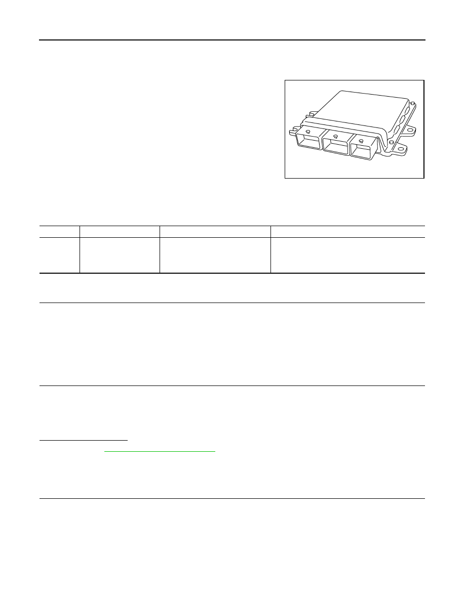
JMBIA0057ZZ
DTC No.
Trouble diagnosis name
DTC detecting condition
Possible cause
P0603
ECM power supply circuit
ECM back up RAM system does not
function properly.
• Harness or connectors
[ECM power supply (back up) circuit is open or
shorted.]
• ECM
Нет комментариевНе стесняйтесь поделиться с нами вашим ценным мнением.
Текст