Infiniti FX35, FX50 (S51). Manual — part 172

AV
INSPECTION AND ADJUSTMENT
AV-461
< BASIC INSPECTION >
[NAVIGATION (TWIN MONITOR)]
C
D
E
F
G
H
I
J
K
L
M
B
A
O
P
CONFIGURATION (AV CONTROL UNIT) : Work Procedure
INFOID:0000000005474977
NOTE:
If “WRITE CONFIGURATION” is unsuccessful, perform “Accessory Number Initialization”. For details, refer to
AV-382, "On Board Diagnosis Function"
.
After performing “Accessory Number Initialization”, reboot the AV control unit to perform “WRITE CONFIGU-
RATION”.
1.
WRITING MODE SELECTION
CONSULT-III Configuration
Select “CONFIGURATION” of “MULTI AV”.
When writing saved data>>GO TO 2.
When writing manually>>GO TO 3.
2.
PERFORM “WRITE CONFIGURATION-CONFIG FILE”
CONSULT-III Configuration
Perform “WRITE CONFIGURATION-Config file”.
>> WORK END
3.
PERFORM “WRITE CONFIGURATION-MANUAL SELECTION”
CONSULT-III Configuration
Select “WRITE CONFIGURATION-Manual selection” to write vehicle specifications into the AV control unit.
For data to write, refer to
AV-461, "CONFIGURATION (AV CONTROL UNIT) : Configuration List"
>> GO TO 4.
4.
OPERATION CHECK
Check that the operation of the AV control unit and camera images (fixed guide lines and predictive course
lines) are normal.
>> WORK END
CONFIGURATION (AV CONTROL UNIT) : Configuration List
INFOID:0000000005474978
CAUTION:
Check vehicle specifications before servicing.
Function
Description
READ CONFIGURATION
• Reads the vehicle configuration of current AV control unit.
• Saves the read vehicle configuration.
WRITE CONFIGURATION-Manual selection
Writes the vehicle configuration with manual selection.
WRITE CONFIGURATION-Config file
Writes the vehicle configuration with saved data.
MANUAL SETTING ITEM
Items
Setting value
STEERING
LHD
RHD
CAMERA SYSTEM
NONE/AVM
REAR CAMERA
REAR+SIDE
SOUND SYSTEM
BASE
BOSE

AV-462
< BASIC INSPECTION >
[NAVIGATION (TWIN MONITOR)]
INSPECTION AND ADJUSTMENT
NOTE:
AVM: Around view monitor
PREDICTIVE COURSE LINE CENTER POSITION ADJUSTMENT
PREDICTIVE COURSE LINE CENTER POSITION ADJUSTMENT : Description
INFOID:0000000005527061
Adjust the center position of the predictive course line of the rear view monitor if it is shifted.
PREDICTIVE COURSE LINE CENTER POSITION ADJUSTMENT : Work Procedure
INFOID:0000000005527062
1.
DRIVING
Drive the vehicle straight ahead 100 m (328.1 ft) or more at a speed of 30 km/h (18.6 MPH) or more.
>> END
CALIBRATING CAMERA IMAGE (AROUND VIEW MONITOR)
CALIBRATING CAMERA IMAGE (AROUND VIEW MONITOR) : Description
INFOID:0000000005474981
• Perform the calibration and perform the writing to the around view monitor control unit when removing and
replacing each camera, removing the camera mounting parts (front grille, door mirror, etc.) and replacing the
around view monitor control unit.
• Align the white lines on the road near the vehicle at the boundary of each camera image by this camera cal-
ibration. The white lines far from the vehicle may not be aligned at the boundary of each camera image. The
farther the line, the greater the difference is.
CALIBRATING CAMERA IMAGE (AROUND VIEW MONITOR) : Work Procedure
INFOID:0000000005474982
Calibration flowchart
Following the flowchart shown in the figure, perform the calibration.
NOTE:
JPNIA1341GB
AV
INSPECTION AND ADJUSTMENT
AV-463
< BASIC INSPECTION >
[NAVIGATION (TWIN MONITOR)]
C
D
E
F
G
H
I
J
K
L
M
B
A
O
P
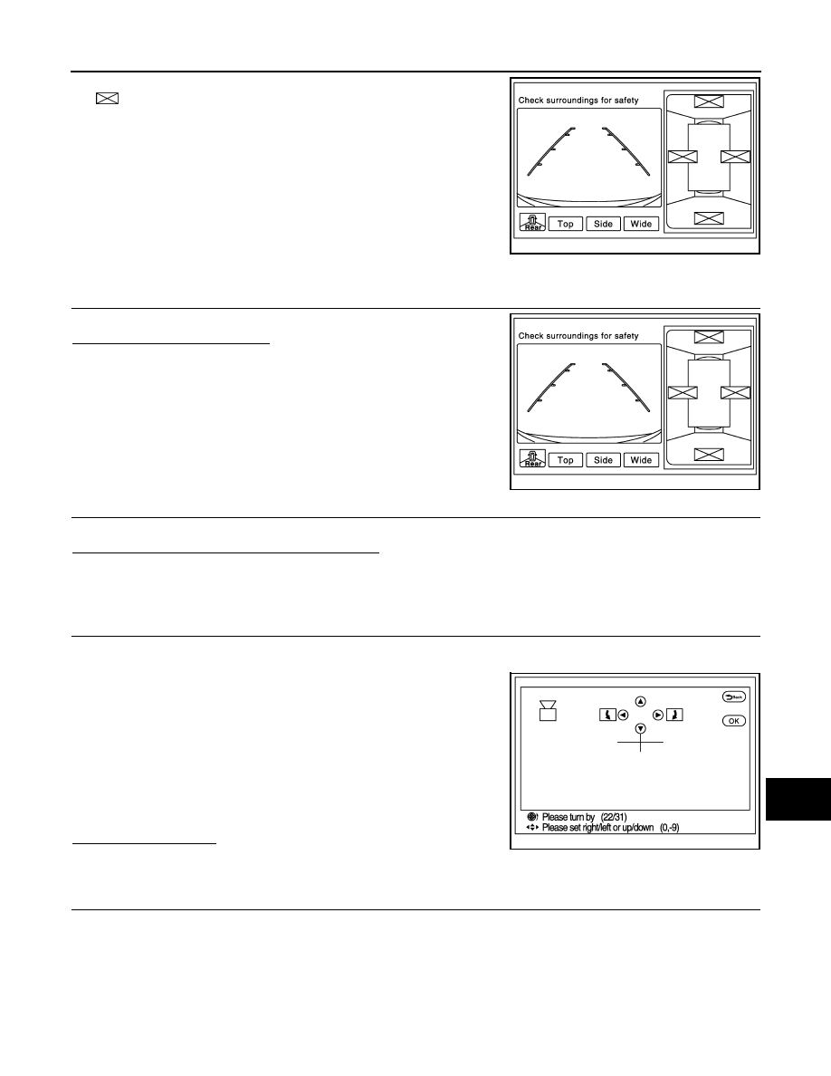
In the un-match display, the un-match camera position is indicated
as “
” on the birds-eye view.
Calibration procedure
1.
AROUND VIEW MONITOR SCREEN CONFIRMATION
Check that there is the un-match display in any camera.
Is the un-match display visible?
YES
>> GO TO 2.
NO
>> GO TO 4.
2.
CHECK THAT AROUND VIEW MONITOR CONTROL UNIT IS REPLACED
Check that the around view monitor control unit is replaced.
Is the around view monitor control unit replaced?
YES
>> GO TO 3.
NO
>> GO TO 5.
3.
RELEASE UN-MATCH DISPLAY (PERFORM ONLY WHEN THE AROUND VIEW MONITOR CONTROL
UNIT IS REPLACED)
1.
Select “Camera Cont.” of Confirmation/ Adjustment mode, and then set to “Calibrating Camera Image”
mode.
2.
Press the “ENTER” switch of the multifunction switch on each
screen of “Rear Camera”, “Front Camera”, “Dr-Side Camera”,
“Pass-Side Camera”.
CAUTION:
• Do never operate the center dial and up/down/left/right
switches. Only press the “ENTER” switch.
• Never perform “Initialize Camera Image Calibration”.
3.
Display the around view monitor screen, and check that there is
no malfunction such as a difference between each camera
image.
Is there a malfunction?
YES
>> Calibration end
NO
>> GO TO 1.
4.
PERFORM SIMPLIFIED CONFIRMATION/ADJUSTMENT BY “FINE TUNING OF BIRDS-EYE VIEW”
1.
Put target line 1 on the ground beside each axle using packing tape, etc.
2.
Put target lines 2 equal to the vehicle total length + approximately 1.0 m (39.3 in) from the vehicle side
(right and left) at approximately 30 cm (11.8 in) away from the vehicle (make the line as parallel with the
vehicle as possible)
JSNIA2378ZZ
JSNIA2378ZZ
JSNIA2379ZZ
AV-464
< BASIC INSPECTION >
[NAVIGATION (TWIN MONITOR)]
INSPECTION AND ADJUSTMENT
Preparation of simplified target line
3.
Select “Camera Cont.” of Confirmation/ Adjustment mode, and then set to “Fine Tuning of Birds-Eye View”
mode.
4.
Select left and right cameras by pressing the “CAMERA” switch, and perform the following confirmation.
-
Check that target line 1 is aligned with the marker on the screen. Overlap the line aligned to the marker
with the upper/lower switches if necessary.
-
Check if there is a difference between target lines 2 between cameras. Adjust target lines 2 to be straight
lines by operating the center dial and left/right switches if necessary.
CAUTION:
•
Never adjust the front camera and rear camera. Only adjust the right and left cameras.
•
Operate the center dial slowly because the changing of the screen takes approximately 1 sec-
ond.
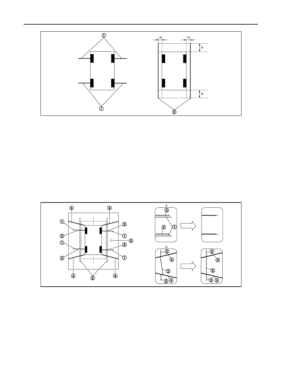
Simplified target line adjustment method
5.
Adjust left and right cameras. Check that the difference between target line 1 and the marker on the
screen, and between target lines 2 is solved.
NOTE:
• It can be initialized to the NISSAN factory default condition with “Initialize Camera Image Calibration” of
“Calibrating Camera Image”.
JSNIA0927ZZ
1.
Target lines 1
2.
Target lines 2
A.
Approx. 30 cm (11.8 in)
B.
Approx. 1.0 m (39.3 in)
JSNIA0929ZZ
1.
Target lines 1
2.
Target lines 2
3.
Marker for target line 1
4.
Boundary between cameras
5.
Crosshairs cursor (mark indicated
the selected camera)
A.
Adjustment method for target lines 1
(right)
B.
Adjustment method for target lines 2
(right)
Нет комментариевНе стесняйтесь поделиться с нами вашим ценным мнением.
Текст