Infiniti FX35, FX50 (S51). Manual — part 1102
HOW TO READ WIRING DIAGRAMS
GI-9
< HOW TO USE THIS MANUAL >
C
D
E
F
G
H
I
J
K
L
M
B
GI
N
O
P
HOW TO READ WIRING DIAGRAMS
Connector Symbols
INFOID:0000000005570618
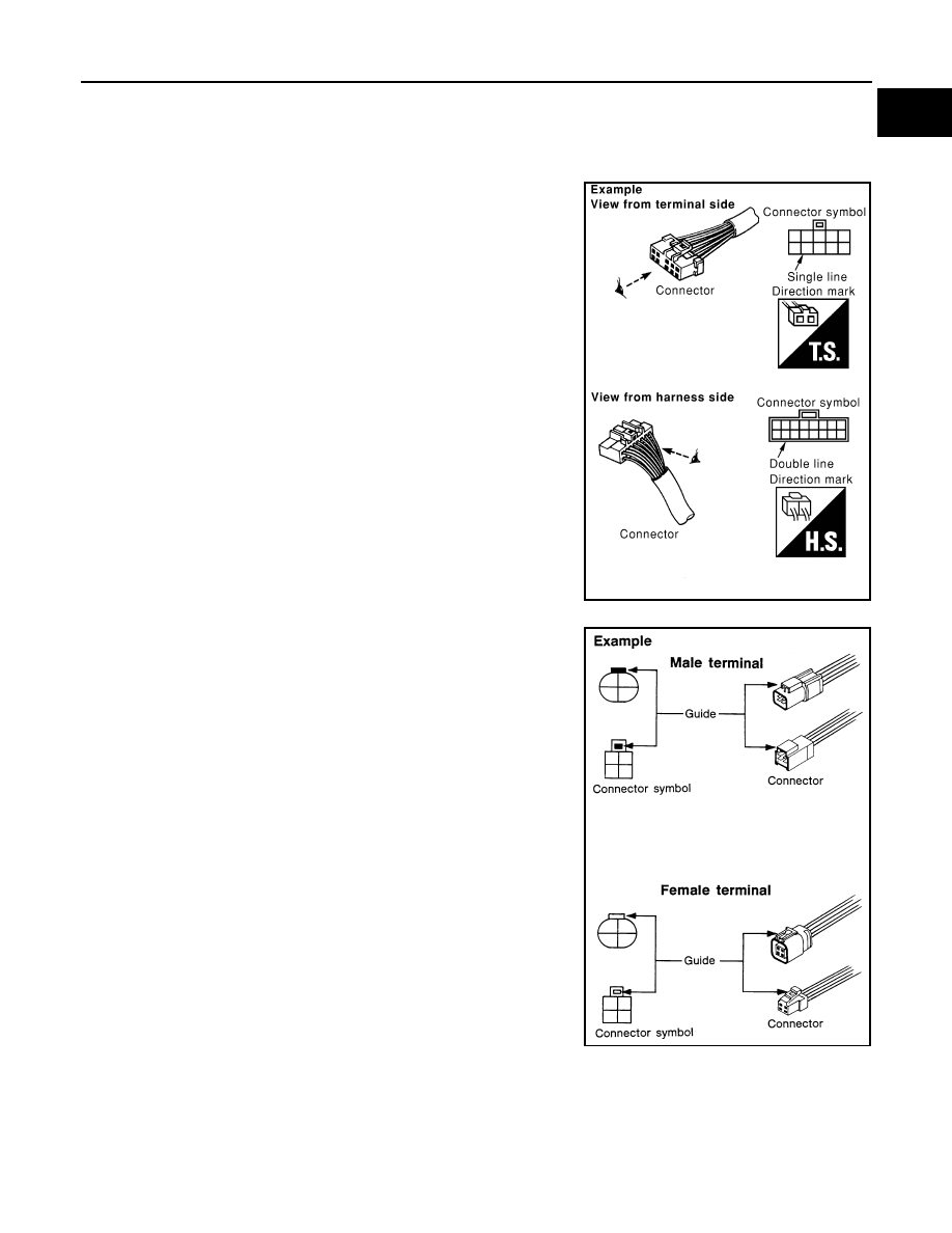
Most of connector symbols in wiring diagrams are shown from the terminal side.
• Connector symbols shown from the terminal side are enclosed by
a single line and followed by the direction mark.
• Connector symbols shown from the harness side are enclosed by
a double line and followed by the direction mark.
• Certain systems and components, especially those related to
OBD, may use a new style slide-locking type harness connector.
For description and how to disconnect, refer to PG section,
“Description”, “HARNESS CONNECTOR”.
• Male and female terminals
Connector guides for male terminals are shown in black and
female terminals in white in wiring diagrams.
SAIA0257E
SGI363
GI-10
< HOW TO USE THIS MANUAL >
HOW TO READ WIRING DIAGRAMS
Sample/Wiring Diagram -Example-
INFOID:0000000005570619
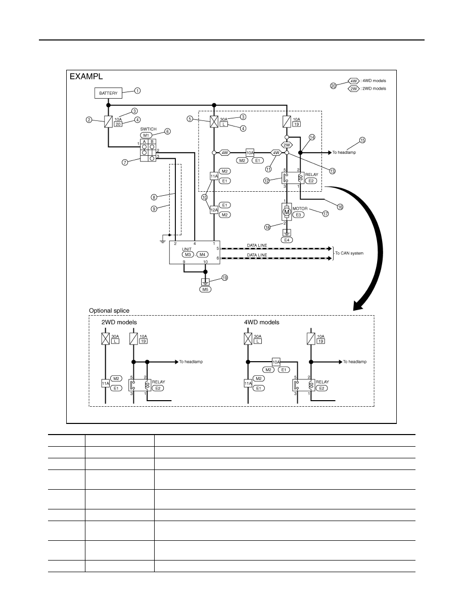
Each section includes wiring diagrams.
Description
JCAWA0150GB
Number
Item
Description
1
Power supply
• This means the power supply of fusible link or fuse.
2
Fuse
• “/” means the fuse.
3
Current rating of fus-
ible link/fuse
• This means the current rating of the fusible link or fuse.
4
Number of fusible link/
fuse
• This means the number of fusible link or fuse location.
5
Fusible link
• “X” means the fusible link.
6
Connector number
• Alphabetic characters show to which harness the connector is placed.
• Numeric characters show the identification number of connectors.
7
Switch
• This shows that continuity exists between terminals 1 and 2 when the switch is in the A
position. Continuity exists between terminals 1 and 3 when the switch is in the B position.
8
Circuit (Wiring)
• This means the wiring.
HOW TO READ WIRING DIAGRAMS
GI-11
< HOW TO USE THIS MANUAL >
C
D
E
F
G
H
I
J
K
L
M
B
GI
N
O
P
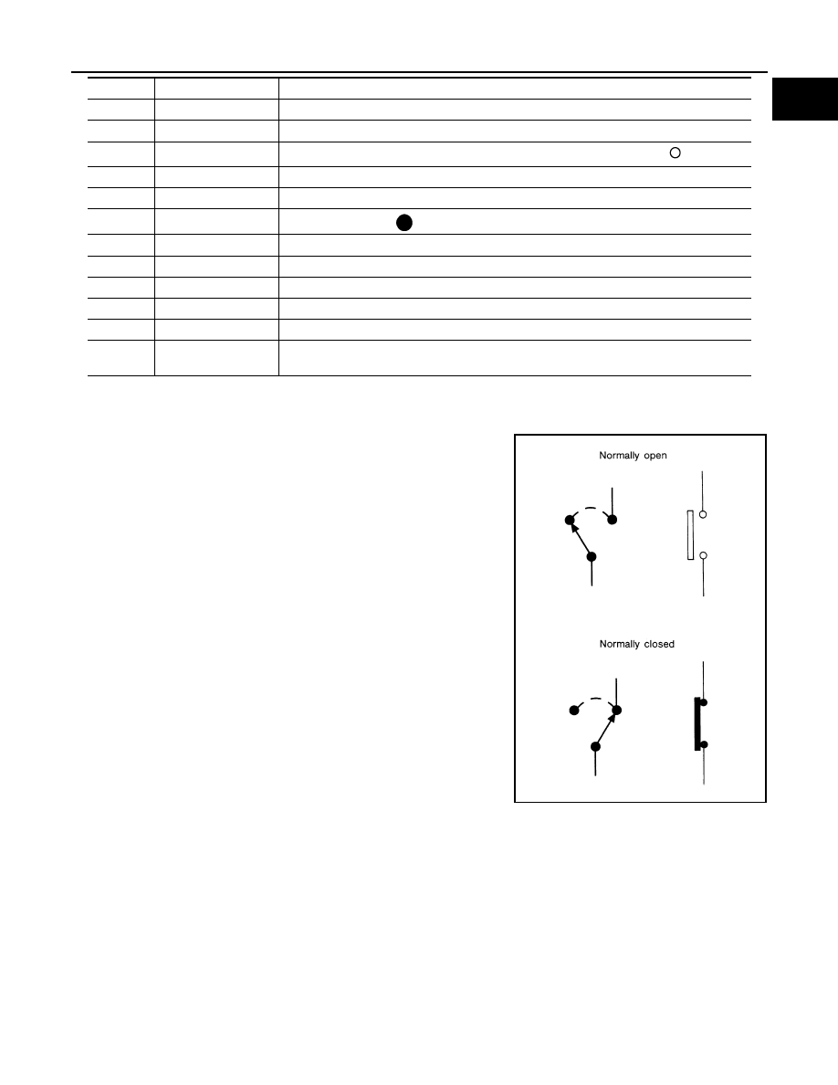
SWITCH POSITIONS
Switches are shown in wiring diagrams as if the vehicle is in the “normal” condition.
A vehicle is in the “normal” condition when:
• ignition switch is “OFF”,
• doors, hood and trunk lid/back door are closed,
• pedals are not depressed, and
• parking brake is released.
MULTIPLE SWITCH
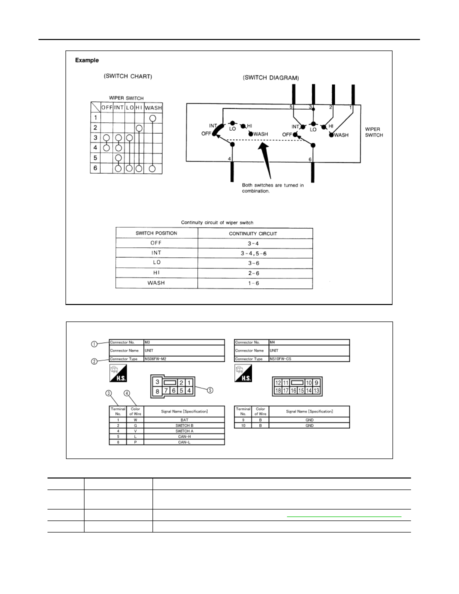
The continuity of multiple switch is described in two ways as shown below.
• The switch chart is used in schematic diagrams.
9
Shielded line
• The line enclosed by broken line circle shows shield wire.
10
Connectors
• This means that a transmission line bypasses two connectors or more.
11
Option abbreviation
• This means the vehicle specifications which layouts the circuit between “
”.
12
Relay
• This shows an internal representation of the relay.
13
Optional splice
• The open circle shows that the splice is optional depending on vehicle application.
14
Splice
• The shaded circle “
” means the splice.
15
System branch
• This shows that the circuit is branched to other systems.
16
Page crossing
• This circuit continues to an adjacent page.
17
Component name
• This shows the name of a component.
18
Terminal number
• This means the terminal number of a connector.
19
Ground (GND)
• This shows the ground connection.
20
Explation of option
description
• This shows a explanation of the option abbreviation used on the same page.
Number
Item
Description
SGI860
GI-12
< HOW TO USE THIS MANUAL >
HOW TO READ WIRING DIAGRAMS
• The switch diagram is used in wiring diagrams.
Connector Information
INFOID:0000000005570620
Description
JSAIA0017GB
Number
Item
Description
1
Connector number
• Alphabetic characters show to which harness the connector is placed.
• Numeric characters show the identification number of connectors.
2
Connector type
• This means the connector number. Refer to
PG-134, "How To Read Harness Layout"
3
Terminal number
• This means the terminal number of a connector.
JCAWA0152GB
Нет комментариевНе стесняйтесь поделиться с нами вашим ценным мнением.
Текст