Infiniti FX35, FX50 (S51). Manual — part 1690
BCM (BODY CONTROL MODULE)
SEC-173
< ECU DIAGNOSIS INFORMATION >
[INTELLIGENT KEY SYSTEM]
C
D
E
F
G
H
I
J
L
M
A
B
SEC
N
O
P
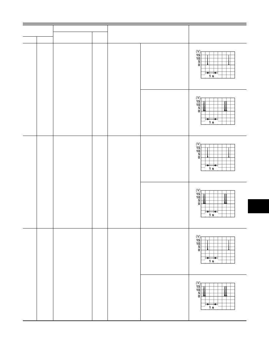
77
(LG)
Ground
Driver door antenna
(+)
Output
When the driver
door request
switch is operat-
ed with ignition
switch OFF
When Intelligent Key is in
the antenna detection area
When Intelligent Key is not
in the antenna detection
area
78
(Y)
Ground
Room antenna 1 (
−
)
(Instrument panel)
Output
Ignition switch
OFF
When Intelligent Key is in
the passenger compart-
ment
When Intelligent Key is not
in the passenger compart-
ment
79
(BR)
Ground
Room antenna 1 (+)
(Instrument panel)
Output
Ignition switch
OFF
When Intelligent Key is in
the passenger compart-
ment
When Intelligent Key is not
in the passenger compart-
ment
Terminal No.
(Wire color)
Description
Condition
Value
(Approx.)
Signal name
Input/
Output
+
–
JMKIA0062GB
JMKIA0063GB
JMKIA0062GB
JMKIA0063GB
JMKIA0062GB
JMKIA0063GB
SEC-174
< ECU DIAGNOSIS INFORMATION >
[INTELLIGENT KEY SYSTEM]
BCM (BODY CONTROL MODULE)
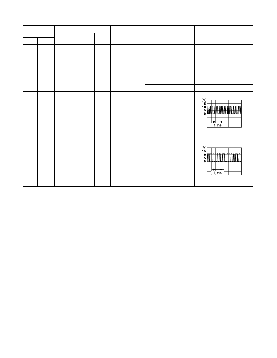
80
(GR)
Ground
NATS antenna amp.
Input/
Output
During waiting
Ignition switch is pressed
while inserting the Intelli-
gent Key into the key slot.
Just after pressing ignition
switch. Pointer of tester should
move.
81
(W)
Ground
NATS antenna amp.
Input/
Output
During waiting
Ignition switch is pressed
while inserting the Intelli-
gent Key into the key slot.
Just after pressing ignition
switch. Pointer of tester should
move.
82
(P)
Ground
Ignition relay [Fuse
block (J/B)] control
Output
Ignition switch
OFF or ACC
0 V
ON
12 V
83
(GR)
Ground
Remote keyless entry
receiver communica-
tion
Input/
Output
During waiting
When operating either button on the Intelligent
Key
Terminal No.
(Wire color)
Description
Condition
Value
(Approx.)
Signal name
Input/
Output
+
–
JMKIA0064GB
JMKIA0065GB
BCM (BODY CONTROL MODULE)
SEC-175
< ECU DIAGNOSIS INFORMATION >
[INTELLIGENT KEY SYSTEM]
C
D
E
F
G
H
I
J
L
M
A
B
SEC
N
O
P
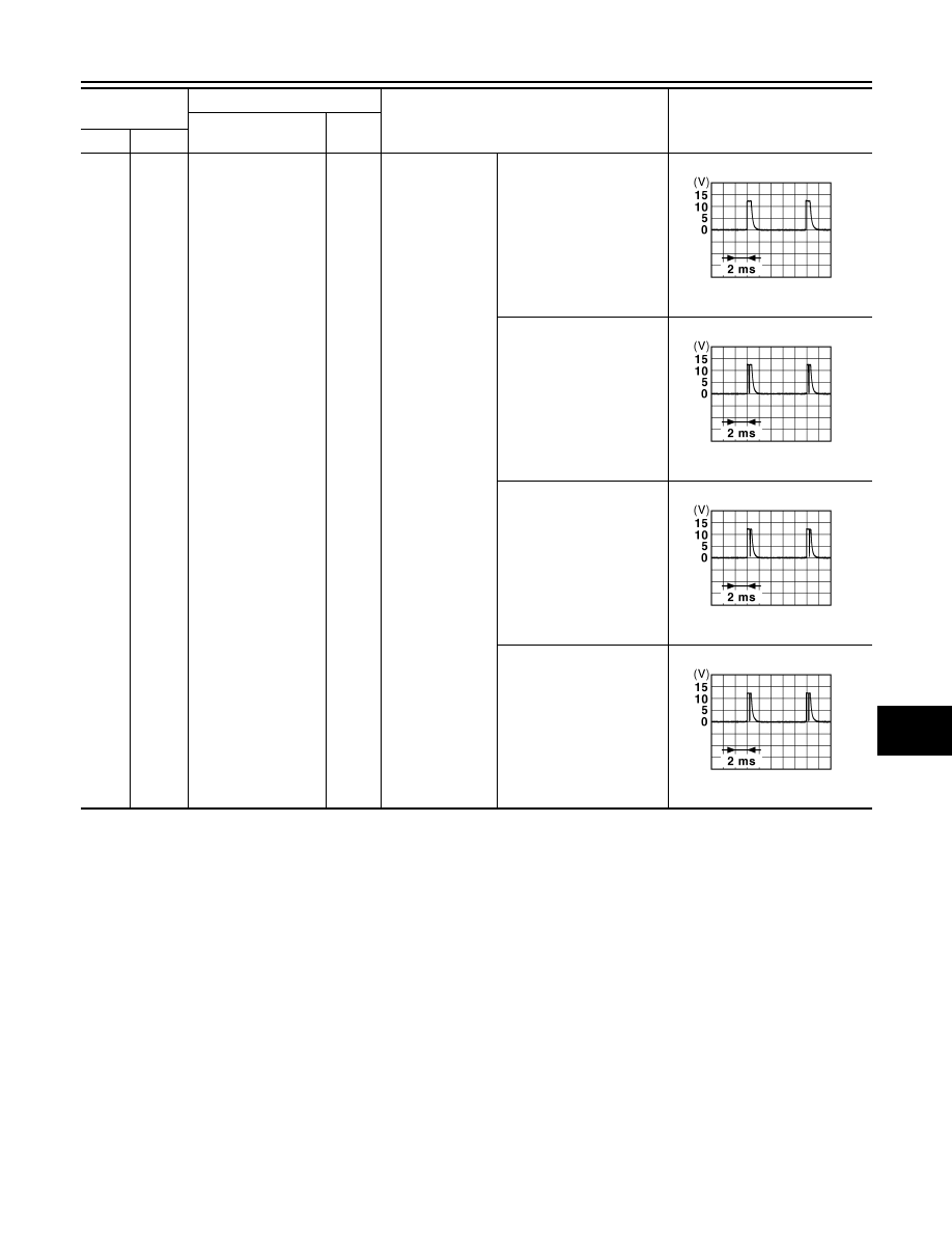
87
(BR)
Ground
Combination switch
INPUT 5
Input
Combination
switch
All switches OFF
(Wiper intermittent dial 4)
1.4 V
Front fog lamp switch ON
(Wiper intermittent dial 4)
1.3 V
Rear wiper switch ON
(Wiper intermittent dial 4)
1.3 V
Any of the conditions below
with all switches OFF
• Wiper intermittent dial 1
• Wiper intermittent dial 2
• Wiper intermittent dial 6
• Wiper intermittent dial 7
1.3 V
Terminal No.
(Wire color)
Description
Condition
Value
(Approx.)
Signal name
Input/
Output
+
–
JPMIA0041GB
JPMIA0037GB
JPMIA0039GB
JPMIA0040GB
SEC-176
< ECU DIAGNOSIS INFORMATION >
[INTELLIGENT KEY SYSTEM]
BCM (BODY CONTROL MODULE)
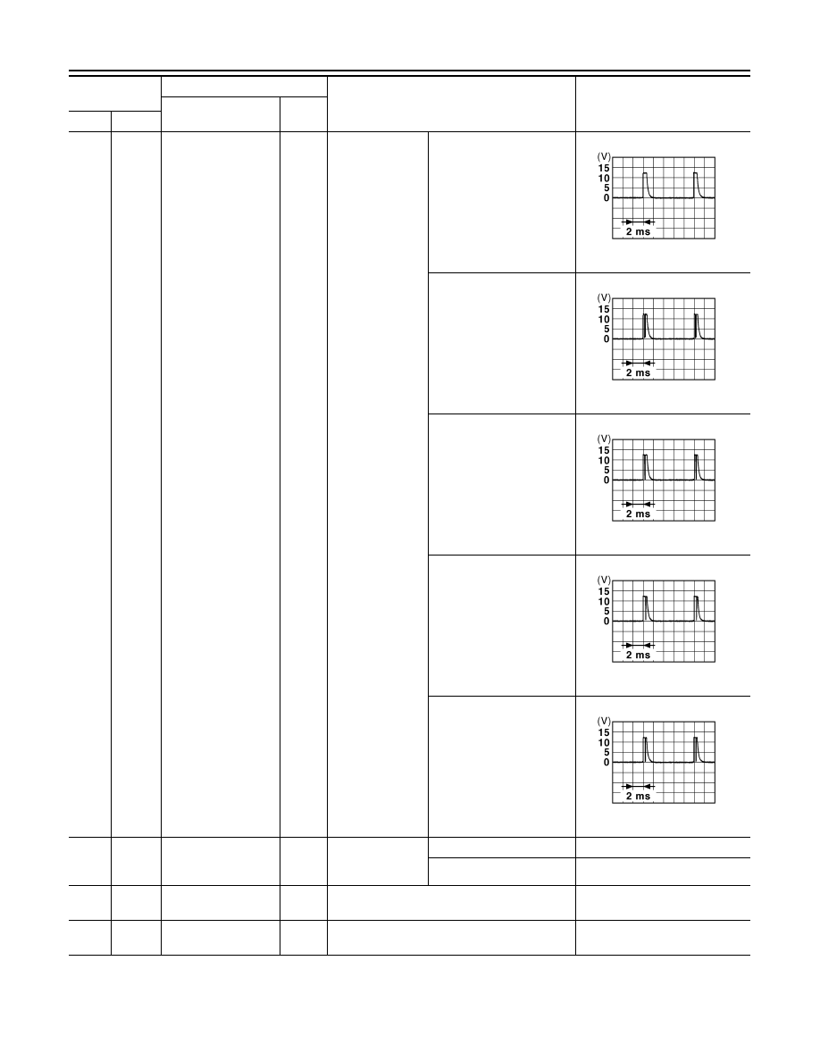
88
(V)
Ground
Combination switch
INPUT 3
Input
Combination
switch
All switches OFF
(Wiper intermittent dial 4)
1.4 V
Lighting switch HI
(Wiper intermittent dial 4)
1.3 V
Lighting switch 2ND
(Wiper intermittent dial 4)
1.3 V
Rear washer switch ON
(Wiper intermittent dial 4)
1.3 V
Any of the conditions below
with all switches OFF
• Wiper intermittent dial 1
• Wiper intermittent dial 2
• Wiper intermittent dial 3
1.3 V
89
(SB)
Ground
Push-button ignition
switch (Push switch)
Input
Push-button igni-
tion switch (Push
switch)
Pressed
0 V
Not pressed
12 V
90
(P)
Ground
CAN-L
Input/
Output
—
—
91
(L)
Ground
CAN-H
Input/
Output
—
—
Terminal No.
(Wire color)
Description
Condition
Value
(Approx.)
Signal name
Input/
Output
+
–
JPMIA0041GB
JPMIA0036GB
JPMIA0037GB
JPMIA0039GB
JPMIA0040GB
Нет комментариевНе стесняйтесь поделиться с нами вашим ценным мнением.
Текст