Infiniti FX35, FX50 (S51). Manual — part 60
AV
PRECAUTIONS
AV-13
< PRECAUTION >
[WITHOUT NAVIGATION]
C
D
E
F
G
H
I
J
K
L
M
B
A
O
P
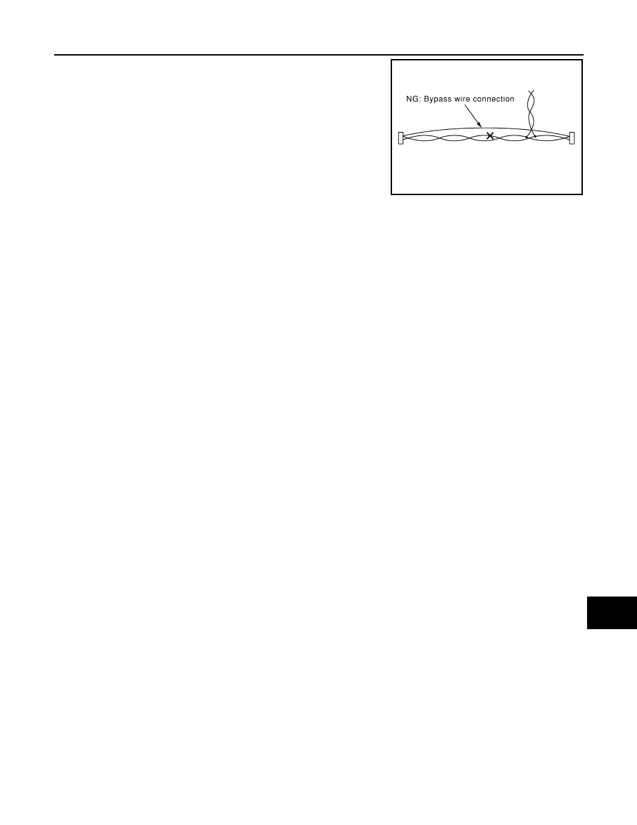
• Do not perform bypass wire connections for the repair parts. (The
spliced wire will become separated and the characteristics of
twisted line will be lost.)
PKIA0307E
AV-14
< PREPARATION >
[WITHOUT NAVIGATION]
PREPARATION
PREPARATION
PREPARATION
Commercial Service Tools
INFOID:0000000005246875
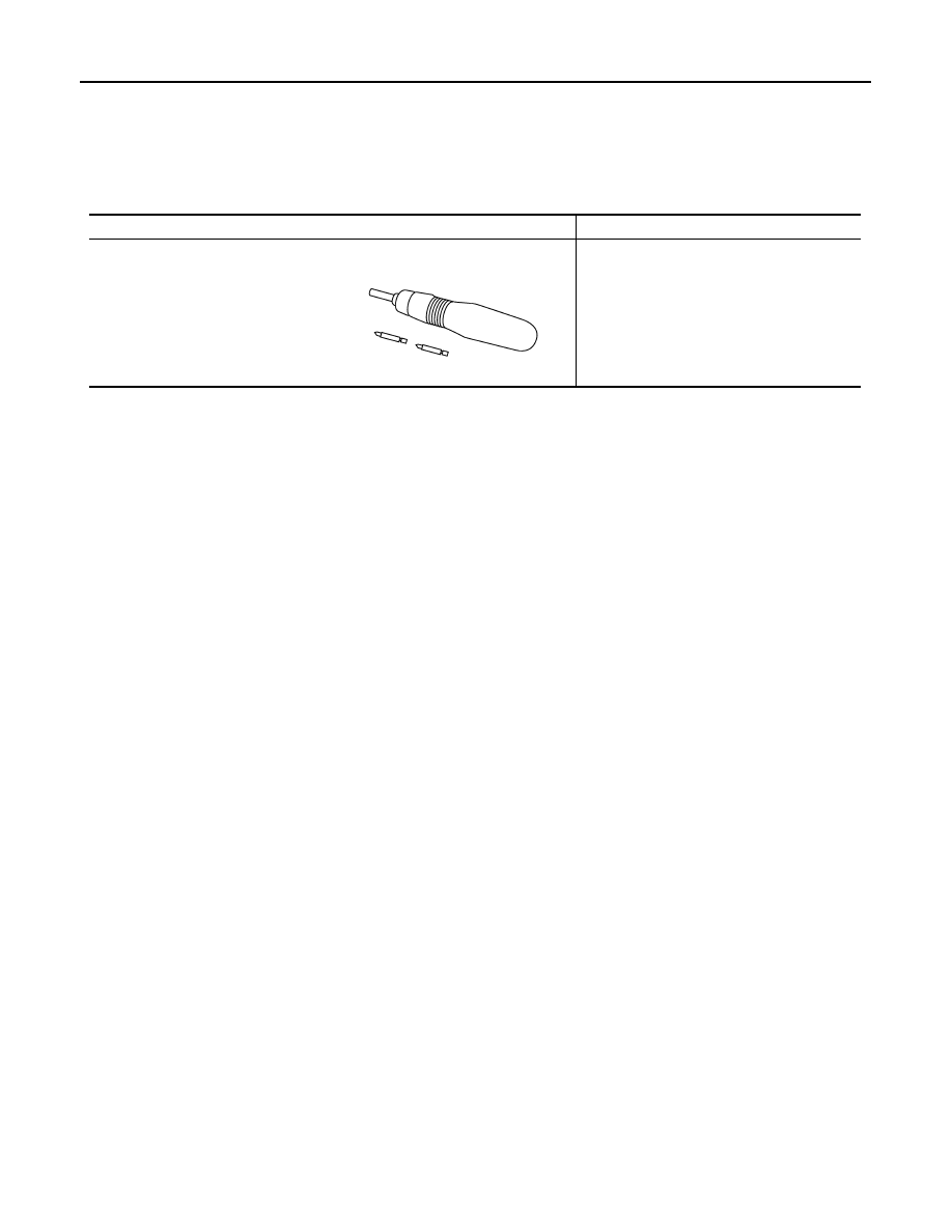
Tool name
Description
Power tool
Loosening screws
PBIC0191E

AV
COMPONENT PARTS
AV-15
< SYSTEM DESCRIPTION >
[WITHOUT NAVIGATION]
C
D
E
F
G
H
I
J
K
L
M
B
A
O
P
SYSTEM DESCRIPTION
COMPONENT PARTS
Component Parts Location
INFOID:0000000005527807
1.
Front squawker RH
2.
Center speaker
3.
Front squawker LH
4.
Front door speaker LH
5.
Rear door speaker LH
6.
Rear squawker LH
7.
BOSE amp.
8.
TEL adapter unit
9.
Woofer
10. Rear view camera
11. Satellite radio tuner
12. TEL antenna
13. Rear squawker RH
14.
Antenna base (antenna amp. and
satellite antenna)
15. Rear door speaker RH
16. Front door speaker RH
17. Front display unit
18. Steering switch
19. Preset switch
20. Auxiliary input jacks
21. USB connector
22. AV control unit
23. Multifunction switch
24. Microphone
A.
Luggage floor (LH side)
B.
Luggage side RH
C.
Console pocket assembly removed
condition
JSNIA2458ZZ

AV-16
< SYSTEM DESCRIPTION >
[WITHOUT NAVIGATION]
COMPONENT PARTS
Component Description
INFOID:0000000005527808
Part name
Description
AV control unit
• Integrates flash memory allowing music data to be stored.
• It is the master unit of the MULTI AV system, and it is connected to each control
unit by communication. It operates each system according to communication
signals from the AV control unit.
• The AV control unit includes the audio, USB connection and vehicle informa-
tion functions.
• It is connected to ECM and unified meter and A/C amp. via CAN communica-
tion to obtain necessary information for the vehicle information function.
• It is connected to BCM via CAN communication transmitting/receiving for the
vehicle settings function.
• It inputs the illumination signals that are required for the display dimming con-
trol.
• It inputs the signals for driving status recognition (vehicle speed, reverse and
parking brake).
• TEL voice signal and voice guidance signal are input from TEL adapter unit.
Front display unit
• Front display image is controlled by the serial communication from AV control
unit.
• It receives the power (signal VCC and inverter VCC) from the AV control unit
and operates.
• RGB image signal is input from AV control unit (RGB, RGB area and RGB syn-
chronizing).
• Composite image signals (auxiliary and camera images) are input from AV
control unit.
• Synchronizing signal (HP, VP) is output to AV control unit.
BOSE amp.
• Inputs sound signal from AV control unit, and outputs sound signal to each
speaker.
• Inputs mode change signal from AV control unit.
Front door speaker
• Outputs sound signal from BOSE amp.
• Outputs high, mid and low range sounds.
Rear door speaker
• Outputs sound signal from BOSE amp.
• Outputs high, mid and low range sounds.
Front squawker
• Outputs sound signal from BOSE amp.
• Outputs mid range sounds.
Rear squawker
• Outputs sound signal from BOSE amp.
• Outputs mid range sounds.
Center speaker
• Outputs sound signal from BOSE amp.
• Outputs high and mid range sounds.
Woofer
• Inputs power (woofer amp. ON signal) and sound signal from BOSE amp.
• Outputs low range sound.
Multifunction switch
• Operation panel is equipped with the centralized switch where audio and aux-
iliary input, etc. operations are integrated.
• Connected with preset switch via cable, and operation signal is transmitted to
AV control unit via AV communication.
Preset switch
• Operation panel is equipped with the centralized switch where audio and air
conditioner, etc. operations are integrated.
• Connected with multifunction switch via cable, and operation signal is transmit-
ted to AV control unit via AV communication.
• The disk ejection operating signal is performed by hardwire.
Rear view camera
• Camera power supply is input from AV control unit.
• The image of vehicle rear view is transmitted to AV control unit.
Steering switch
• Operations for audio and hands-free phone are possible.
• Steering switch signal (operation signal) is output to AV control unit.
Microphone
• Used for hands-free phone operation.
• Microphone signal is transmitted to TEL adapter unit.
• Power (Microphone VCC) is supplied from TEL adapter unit.
Нет комментариевНе стесняйтесь поделиться с нами вашим ценным мнением.
Текст