Infiniti FX35, FX50 (S51). Manual — part 1093
SERVICE DATA AND SPECIFICATIONS (SDS)
FSU-19
< SERVICE DATA AND SPECIFICATIONS (SDS)
[2WD]
C
D
F
G
H
I
J
K
L
M
A
B
FSU
N
O
P
SERVICE DATA AND SPECIFICATIONS (SDS)
SERVICE DATA AND SPECIFICATIONS (SDS)
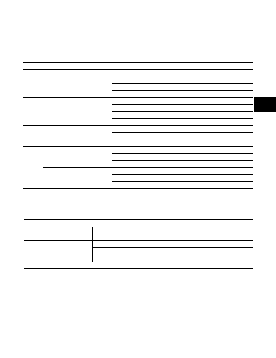
Wheel Alignment
INFOID:0000000005246433
Measure value under unladen* conditions.
*: Fuel, engine coolant and lubricant are full. Spare tire, jack, hand tools and mats are in designated positions.
Ball Joint
INFOID:0000000005246434
Item
Standard
Camber
Degree minute (Decimal degree)
Minimum
–1
°
05
′
(–1.08
°
)
Nominal
−
0
°
20
′
(
−
0.33
°
)
Maximum
0
°
25
′
(0.41
°
)
Left and right difference
0
°
33
′
(0.55
°
) or less
Caster
Degree minute (Decimal degree)
Minimum
2
°
55
′
(2.92
°
)
Nominal
3
°
40
′
(3.67
°
)
Maximum
4
°
25
′
(4.41
°
)
Left and right difference
0
°
39
′
(0.65
°
) or less
Kingpin inclination
Degree minute (Decimal degree)
Minimum
7
°
55
′
(7.92
°
)
Nominal
8
°
40
′
(8.67
°
)
Maximum
9
°
25
′
(9.41
°
)
Toe-in
Total toe-in
Distance
Minimum
In 1 mm (0.04 in)
Nominal
In 2 mm (0.08 in)
Maximum
In 3 mm (0.11 in)
Toe angle (left wheel or right wheel)
Degree minute (Decimal Degree)
Minimum
In 0
°
02
′
12
″
(0.04
°
)
Nominal
In 0
°
04
′
24
″
(0.07
°
)
Maximum
In 0
°
06
′
36
″
(0.11
°
)
Item
Standard
Swing torque
Transverse link
0.5 – 3.6 N·m (0.06 – 0.36 kg-m, 5 – 31 in-lb)
Upper link
0 – 2.0 N·m (0 – 0.20 kg-m, 0 – 17 in-lb)
Measurement on spring balance
Transverse link
7.8 – 56.3 N (0.8 – 5.7 kg, 1.8 – 12.6 lb)
Upper link
0 – 61.5 N (0 – 6.2 kg, 0 – 13.8 lb)
Rotating torque
Transverse link
0.5 – 3.9 N·m (0.06 – 0.39 kg-m, 5 – 34 in-lb)
Axial end play
0 mm (0 in)
FSU-20
< SERVICE DATA AND SPECIFICATIONS (SDS)
[2WD]
SERVICE DATA AND SPECIFICATIONS (SDS)
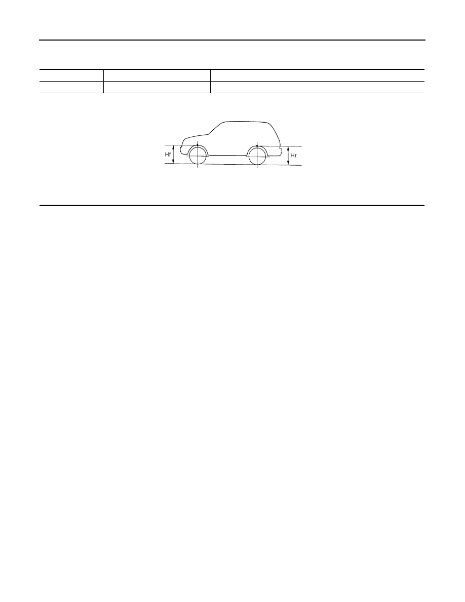
Wheel Height
INFOID:0000000005246435
Measure value under unladen* conditions
*: Fuel, engine coolant and lubricant are full. Spare tire, jack, hand tools and mats are in designated positions.
Tire size
265/60R18
265/50R20
Front (Hf)
831 mm (32.72 in)
832 mm (32.76 in)
SFA746B
NOISE, VIBRATION AND HARSHNESS (NVH) TROUBLESHOOTING
FSU-21
< SYMPTOM DIAGNOSIS >
[AWD]
C
D
F
G
H
I
J
K
L
M
A
B
FSU
N
O
P
SYMPTOM DIAGNOSIS
NOISE, VIBRATION AND HARSHNESS (NVH) TROUBLESHOOTING
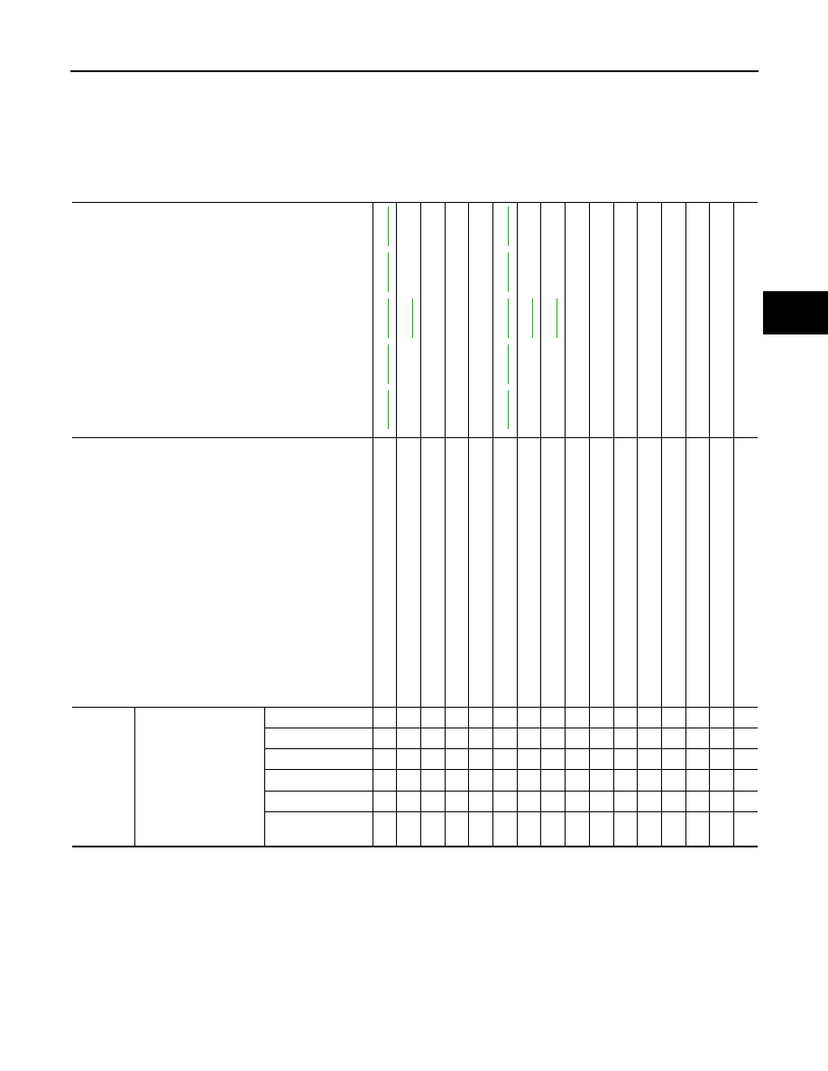
NVH Troubleshooting Chart
INFOID:0000000005246436
Use chart below to find the cause of the symptom. If necessary, repair or replace these parts.
×
: Applicable
Reference page
,
,
,
,
—
—
—
,
,
,
,
NVH in DLN section.
NVH in RFD
section.
NVH in
F
AX an
d F
S
U
s
e
c
ti
o
ns
.
NVH in WT section.
NVH in WT section.
NVH in F
AX section.
NVH in B
R
section.
NVH in S
T
section.
Possible cause and SUSPECTED PARTS
Im
p
rop
er i
n
s
tal
la
tio
n
,
loo
s
ene
s
s
S
hoc
k
ab
so
rbe
r d
e
fo
rma
tio
n,
da
ma
ge
o
r de
fle
c
tion
B
u
s
h
in
g
or m
o
u
n
ting
d
e
te
rio
rati
o
n
P
a
rt
s interference
S
p
ri
ng
fat
ig
u
e
S
us
pe
ns
ion
lo
os
en
es
s
In
co
rrec
t wh
ee
l a
lig
nm
en
t
S
tab
iliz
er b
a
r f
a
ti
gu
e
P
R
OPE
LLE
R SHAFT
DIFFERENTIAL
F
R
ONT
AXLE
AND FRONT S
U
SPENSION
TI
RE
ROAD
WHEEL
DRIV
E SHAFT
BR
AK
E
S
T
EERING
Symptom
FRONT SUSPENSION
Noise
×
×
×
×
×
×
×
×
×
×
×
×
×
×
Shake
×
×
×
×
×
×
×
×
×
×
×
×
Vibration
×
×
×
×
×
×
×
×
×
×
Shimmy
×
×
×
×
×
×
×
×
×
×
Judder
×
×
×
×
×
×
×
×
Poor quality ride or
handling
×
×
×
×
×
×
×
×
×
×
FSU-22
< PRECAUTION >
[AWD]
PRECAUTIONS
PRECAUTION
PRECAUTIONS
Precaution for Supplemental Restraint System (SRS) "AIR BAG" and "SEAT BELT
PRE-TENSIONER"
INFOID:0000000005548669
The Supplemental Restraint System such as “AIR BAG” and “SEAT BELT PRE-TENSIONER”, used along
with a front seat belt, helps to reduce the risk or severity of injury to the driver and front passenger for certain
types of collision. This system includes seat belt switch inputs and dual stage front air bag modules. The SRS
system uses the seat belt switches to determine the front air bag deployment, and may only deploy one front
air bag, depending on the severity of a collision and whether the front occupants are belted or unbelted.
Information necessary to service the system safely is included in the “SRS AIR BAG” and “SEAT BELT” of this
Service Manual.
WARNING:
• To avoid rendering the SRS inoperative, which could increase the risk of personal injury or death in
the event of a collision which would result in air bag inflation, all maintenance must be performed by
an authorized NISSAN/INFINITI dealer.
• Improper maintenance, including incorrect removal and installation of the SRS, can lead to personal
injury caused by unintentional activation of the system. For removal of Spiral Cable and Air Bag
Module, see the “SRS AIR BAG”.
• Do not use electrical test equipment on any circuit related to the SRS unless instructed to in this
Service Manual. SRS wiring harnesses can be identified by yellow and/or orange harnesses or har-
ness connectors.
PRECAUTIONS WHEN USING POWER TOOLS (AIR OR ELECTRIC) AND HAMMERS
WARNING:
• When working near the Air Bag Diagnosis Sensor Unit or other Air Bag System sensors with the
ignition ON or engine running, DO NOT use air or electric power tools or strike near the sensor(s)
with a hammer. Heavy vibration could activate the sensor(s) and deploy the air bag(s), possibly
causing serious injury.
• When using air or electric power tools or hammers, always switch the ignition OFF, disconnect the
battery, and wait at least 3 minutes before performing any service.
Precaution Necessary for Steering Wheel Rotation after Battery Disconnect
INFOID:0000000005548672
NOTE:
• Before removing and installing any control units, first turn the push-button ignition switch to the LOCK posi-
tion, then disconnect both battery cables.
• After finishing work, confirm that all control unit connectors are connected properly, then re-connect both
battery cables.
• Always use CONSULT-III to perform self-diagnosis as a part of each function inspection after finishing work.
If a DTC is detected, perform trouble diagnosis according to self-diagnosis results.
For vehicle with steering lock unit, if the battery is disconnected or discharged, the steering wheel will lock and
cannot be turned.
If turning the steering wheel is required with the battery disconnected or discharged, follow the operation pro-
cedure below before starting the repair operation.
OPERATION PROCEDURE
1.
Connect both battery cables.
NOTE:
Supply power using jumper cables if battery is discharged.
2.
Turn the push-button ignition switch to ACC position.
(At this time, the steering lock will be released.)
3.
Disconnect both battery cables. The steering lock will remain released with both battery cables discon-
nected and the steering wheel can be turned.
4.
Perform the necessary repair operation.
Нет комментариевНе стесняйтесь поделиться с нами вашим ценным мнением.
Текст