Infiniti FX35, FX50 (S51). Manual — part 900
ECM
EC-1141
< ECU DIAGNOSIS INFORMATION >
[VK50VE]
C
D
E
F
G
H
I
J
K
L
M
A
EC
N
P
O
51
(O)
128
(B)
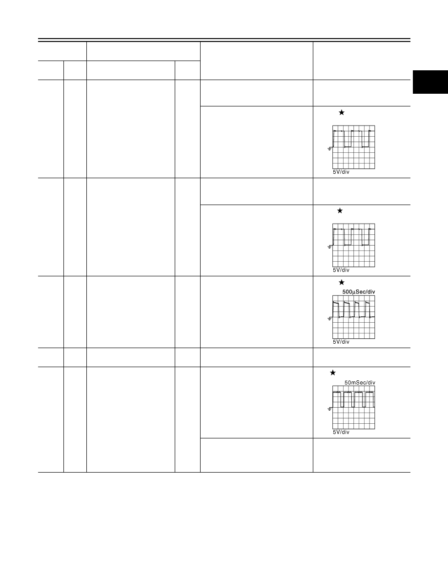
Intake valve timing control so-
lenoid valve (bank 1)
Output
[Engine is running]
• Warm-up condition
• Idle speed
BATTERY VOLTAGE
(11 - 14 V)
[Engine is running]
• Warm-up condition
• Engine speed: 2,000rpm
7 - 12 V
52
(L)
128
(B)
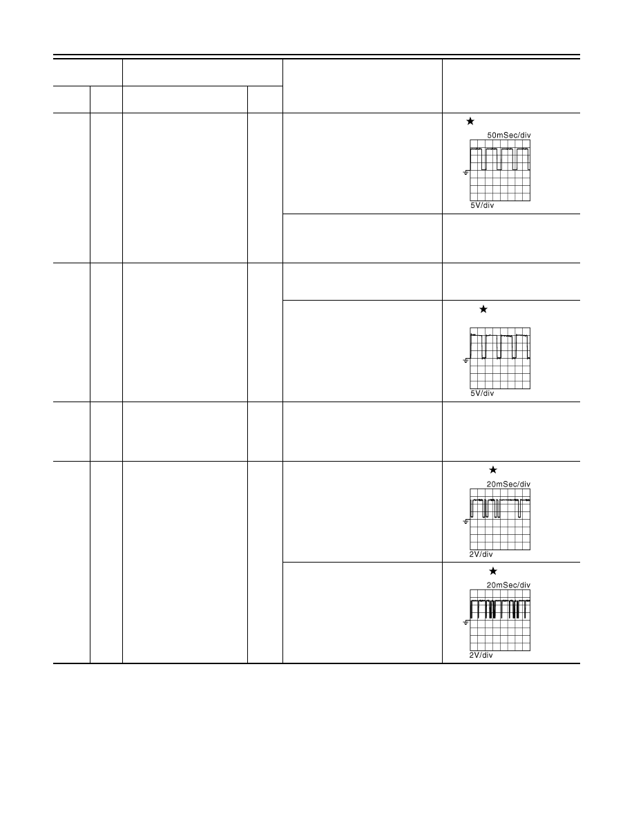
Intake valve timing control so-
lenoid valve (bank 2)
Output
[Engine is running]
• Warm-up condition
• Idle speed
BATTERY VOLTAGE
(11 - 14 V)
[Engine is running]
• Warm-up condition
• Engine speed: 2,000rpm
7 - 12V
53
(BR)
128
(B)
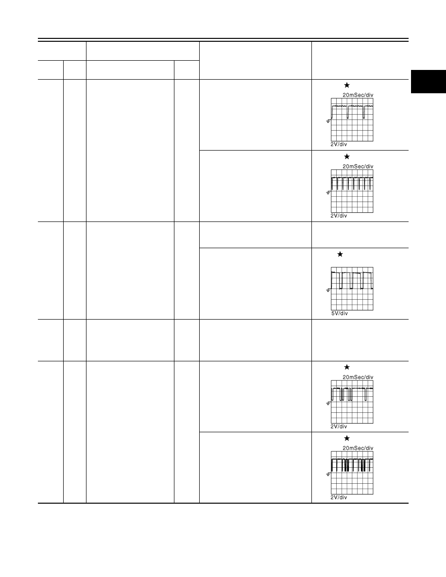
Throttle control motor (bank 1)
(Close)
Output
[Ignition switch: ON]
• Engine: Stopped
• Selector lever: D position
• Accelerator pedal: In the middle of
releasing operation
0 - 14 V
54
(B)
—
ECM ground
—
—
—
55
(P)
128
(B)
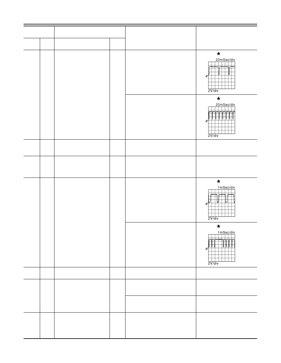
Heated oxygen sensor 2 heat-
er (bank 2)
Output
[Engine is running]
• Engine speed: Below 3,600 rpm after
the following conditions are met
- Engine: after warming up
- Keeping the engine speed between
3,500 and 4,000 rpm for 1 minute
and at idle for 1 minute under no load
10 V
[Ignition switch: ON]
• Engine: Stopped
[Engine is running]
• Engine speed: Above 3,600 rpm
BATTERY VOLTAGE
(11 - 14 V)
Terminal No.
(Wire color)
Description
Condition
Value
(Approx.)
+
–
Signal name
Input/
Output
JMBIA0038GB
JMBIA0038GB
JMBIA0033GB
JMBIA0037GB
EC-1142
< ECU DIAGNOSIS INFORMATION >
[VK50VE]
ECM
56
(R)
128
(B)
Heated oxygen sensor 2 heat-
er (bank 1)
Output
[Engine is running]
• Engine speed: Below 3,600 rpm after
the following conditions are met
- Engine: after warming up
- Keeping the engine speed between
3,500 and 4,000 rpm for 1 minute
and at idle for 1 minute under no load
10 V
[Ignition switch: ON]
• Engine: Stopped
[Engine is running]
• Engine speed: Above 3,600 rpm
BATTERY VOLTAGE
(11 - 14 V)
57
(Y)
128
(B)
Exhaust valve timing control
solenoid valve (bank 2)
Output
[Engine is running]
• Warm-up condition
• Idle speed
BATTERY VOLTAGE
(11 - 14 V)
[Engine is running]
• Warm-up condition
• Around 2,500 rpm while the engine
speed is rising
7 - 12 V
58
(B)
—
Sensor ground
[Camshaft position sensor
(bank 1)/ Exhaust valve timing
control position sensor (bank
1)]
—
—
—
59
(W)
58
(B)
Camshaft position sensor
(bank 1)
Input
[Engine is running]
• Warm-up condition
• Idle speed
NOTE:
The pulse cycle changes depending
on rpm at idle
3.0 - 5.0 V
[Engine is running]
• Engine speed: 2,000 rpm
3.0 - 5.0 V
Terminal No.
(Wire color)
Description
Condition
Value
(Approx.)
+
–
Signal name
Input/
Output
JMBIA0037GB
JMBIA0034GB
JMBIA0045GB
JMBIA0046GB
ECM
EC-1143
< ECU DIAGNOSIS INFORMATION >
[VK50VE]
C
D
E
F
G
H
I
J
K
L
M
A
EC
N
P
O
60
(G)
58
(B)
Exhaust valve timing control
position sensor (bank 1)
Input
[Engine is running]
• Warm-up condition
• Idle speed
NOTE:
The pulse cycle changes depending
on rpm at idle
4.0 - 5.0 V
[Engine is running]
• Warm-up condition
• Engine speed: 2,000 rpm
4.0 - 5.0 V
61
(G)
128
(B)
Exhaust valve timing control
solenoid valve (bank 1)
Output
[Engine is running]
• Warm-up condition
• Idle speed
BATTERY VOLTAGE
(11 - 14 V)
[Engine is running]
• Warm-up condition
• Around 2,500 rpm while the engine
speed is rising
7 - 12 V
62
(O)
—
Sensor ground
[Camshaft position sensor
(bank 2)/ Exhaust valve timing
control position sensor (bank
2)]
—
—
—
63
(BR)
62
(O)
Camshaft position sensor
(bank 2)
Input
[Engine is running]
• Warm-up condition
• Idle speed
NOTE:
The pulse cycle changes depending
on rpm at idle
3.0 - 5.0 V
[Engine is running]
• Engine speed: 2,000 rpm
3.0 - 5.0 V
Terminal No.
(Wire color)
Description
Condition
Value
(Approx.)
+
–
Signal name
Input/
Output
JMBIA0043GB
JMBIA0044GB
JMBIA0034GB
JMBIA0045GB
JMBIA0046GB
EC-1144
< ECU DIAGNOSIS INFORMATION >
[VK50VE]
ECM
64
(P)
62
(O)
Exhaust valve timing control
position sensor (bank 2)
Input
[Engine is running]
• Warm-up condition
• Idle speed
NOTE:
The pulse cycle changes depending
on rpm at idle
4.0 - 5.0 V
[Engine is running]
• Warm-up condition
• Engine speed: 2,000 rpm
4.0 - 5.0 V
65
(LG)
128
(B)
VVEL actuator motor relay
abort signal
(VVEL control module)
Output
[Engine is running]
• Warm-up condition
• Idle speed
0 V
66
(GR)
—
Sensor ground
(Power steering pressure sen-
sor/ Refrigerant pressure sen-
sor)
—
—
—
67
(Y)
68
(B)
Crankshaft position sensor
Input
[Engine is running]
• Warm-up condition
• Idle speed
NOTE:
The pulse cycle changes depending
on rpm at idle
4.0 - 5.0 V
[Engine is running]
• Engine speed: 2,000 rpm
4.0 - 5.0 V
68
(B)
—
Sensor ground
(Crankshaft position sensor)
—
—
—
69
(W)
70
(B)
Manifold absolute pressure
sensor
Input
[Engine is running]
• Warm-up condition
• Idle speed
1.2 V
[Engine is running]
• Warm-up condition
• Engine speed: 2,000 rpm
1.5 V
70
(B)
—
Sensor ground
[Battery current sensor/ EVAP
control system pressure sen-
sor/ Manifold absolute pres-
sure sensor]
—
—
—
Terminal No.
(Wire color)
Description
Condition
Value
(Approx.)
+
–
Signal name
Input/
Output
JMBIA0043GB
JMBIA0044GB
JMBIA0041GB
JMBIA0042GB
Нет комментариевНе стесняйтесь поделиться с нами вашим ценным мнением.
Текст