Infiniti FX35, FX50 (S51). Manual — part 1245
INL-180
< SYMPTOM DIAGNOSIS >
INTERIOR LIGHTING SYSTEM SYMPTOMS
SYMPTOM DIAGNOSIS
INTERIOR LIGHTING SYSTEM SYMPTOMS
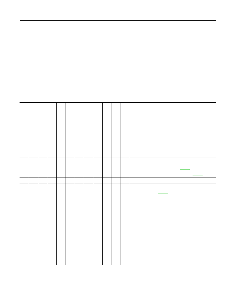
Symptom Table
INFOID:0000000005245623
CAUTION:
Perform the self-diagnosis with CONSULT-III before the symptom diagnosis. Perform the trouble diag-
nosis if any DTC are detected.
SYMPTOMS BY ITEM
1.
Identify the malfunctioning by checking each lamp (whether it can turn ON or not).
2.
Check the malfunction combinations.
3.
Identify the malfunctioning part from the agreed combination and repair or replace the part.
NOTE:
When a lamp other than those in the following table is not turned ON/OFF, check the bulb, the lamp housing,
and the direct circuit.
Malfunction item:
×
*1: Map lamp main switch ALL ON or DOOR
*2: Refer to
for linked illuminations.
Ma
p l
am
p
s
*1
Pers
on
al
l
a
mp
s
*1
Ce
nt
er c
o
n
s
o
le
ind
ire
ct
ill
um
in
ati
o
n
V
a
nit
y
mirror lamp
Foo
t l
a
mp
s
Pu
sh
-bu
tton
i
gni
tio
n
sw
itch
il
lu
m
in
a
ti
on
Mo
od
la
mp
(Rea
r d
o
o
r arm
res
t)
Pu
dd
le la
mp
s
Mo
od
la
mp
(F
ront
do
or
arm
res
t)
Il
lum
in
a
tion
s
*2
(L
in
ke
d wi
th
ho
sp
it
a
lit
y l
ig
h
ti
ng
)
St
e
p
l
a
m
p
s
Lu
gg
ag
e ro
om
la
mp
s
Inspection item (Reference)
×
×
×
×
×
×
×
×
×
×
×
×
Interior room lamp power supply circuit (
×
×
×
×
×
×
×
×
×
×
1.
Power supply and ground circuit of total illumination
control unit (
2.
Battery saver signal circuit (
×
×
×
×
×
×
×
Hospitality lighting power supply 1 circuit (
×
×
Hospitality lighting power supply 2 circuit (
×
×
Map lamp main switch circuit (
×
Map lamp circuit (
)
×
Personal lamp circuit (
×
Center console indirect illumination circuit (
)
×
The lamp housing and the direct circuit (
×
Foot lamp circuit (
×
Push-button ignition switch illumination circuit (
×
Mood lamp (Rear door armrest) circuit (
)
×
Puddle lamp circuit (
×
Mood lamp (Front door armrest) circuit (
)
×
1.
Hospitality lighting power supply 3 circuit (
)
2.
Hospitality illumination circuit (
×
Step lamp circuit (
×
The lamp housing and the direct circuit (

INTERIOR LIGHTING SYSTEM SYMPTOMS
INL-181
< SYMPTOM DIAGNOSIS >
C
D
E
F
G
H
I
J
K
M
A
B
INL
N
O
P
SYMPTOMS BY FUNCTION
Symptom
Inspection item (Reference)
When any door is opened, applicable map lamp or personal lamp is not
turned ON.
(It is turned ON when turning the map lamp main switch ALL ON.)
Door switch circuit (
Interior room lamp timer does not activate.
(It is turned ON/OFF when turning the map lamp main switch ALL ON/
OFF.)
Room lamp timer circuit (
).
Illuminations are not turned ON when tail lamp is ON.
[They are turned ON when hospitality lighting is operated. (Hospitality light-
ing functioning table “Scene 3”)]
Tail lamp signal circuit (
)
Brightness of illuminations is not adjustable by the illumination control
switch when tail lamp is ON.
(Meter illumination control is normal.)
Illumination control signal circuit (
)
Interior room lamp battery saver does not activate.
Check the interior room lamp battery saver setting. (
)
INL-182
< PRECAUTION >
PRECAUTIONS
PRECAUTION
PRECAUTIONS
Precaution for Supplemental Restraint System (SRS) "AIR BAG" and "SEAT BELT
PRE-TENSIONER"
INFOID:0000000005245624
The Supplemental Restraint System such as “AIR BAG” and “SEAT BELT PRE-TENSIONER”, used along
with a front seat belt, helps to reduce the risk or severity of injury to the driver and front passenger for certain
types of collision. This system includes seat belt switch inputs and dual stage front air bag modules. The SRS
system uses the seat belt switches to determine the front air bag deployment, and may only deploy one front
air bag, depending on the severity of a collision and whether the front occupants are belted or unbelted.
Information necessary to service the system safely is included in the “SRS AIR BAG” and “SEAT BELT” of this
Service Manual.
WARNING:
• To avoid rendering the SRS inoperative, which could increase the risk of personal injury or death in
the event of a collision which would result in air bag inflation, all maintenance must be performed by
an authorized NISSAN/INFINITI dealer.
• Improper maintenance, including incorrect removal and installation of the SRS, can lead to personal
injury caused by unintentional activation of the system. For removal of Spiral Cable and Air Bag
Module, see the “SRS AIR BAG”.
• Do not use electrical test equipment on any circuit related to the SRS unless instructed to in this
Service Manual. SRS wiring harnesses can be identified by yellow and/or orange harnesses or har-
ness connectors.
PRECAUTIONS WHEN USING POWER TOOLS (AIR OR ELECTRIC) AND HAMMERS
WARNING:
• When working near the Air Bag Diagnosis Sensor Unit or other Air Bag System sensors with the
ignition ON or engine running, DO NOT use air or electric power tools or strike near the sensor(s)
with a hammer. Heavy vibration could activate the sensor(s) and deploy the air bag(s), possibly
causing serious injury.
• When using air or electric power tools or hammers, always switch the ignition OFF, disconnect the
battery, and wait at least 3 minutes before performing any service.
MAP LAMP
INL-183
< REMOVAL AND INSTALLATION >
C
D
E
F
G
H
I
J
K
M
A
B
INL
N
O
P
REMOVAL AND INSTALLATION
MAP LAMP
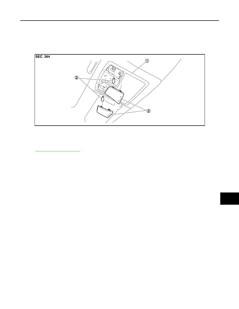
Exploded View
INFOID:0000000005245625
Removal and Installation
INFOID:0000000005245626
for the map lamp assembly installation/removal.
Replacement
INFOID:0000000005245627
CAUTION:
• Disconnect the battery negative terminal or remove the fuse.
• Never touch the glass of bulb directly by hand. Keep grease and other oily matters away from it.
Never touch bulb by hand while it is lit or right after it turns OFF.
• Never leave bulb out of lamp reflector for a long time because dust, moisture, smoke, etc. may affect
the performance of lamp. When replacing bulb, always replace it with new one.
MAP LAMP BULB
1.
Insert any appropriate tool into the gap between the lens. Remove the lens.
2.
Remove the bulb.
1.
Map lamp assembly
2.
Bulb
3.
Lens
JPLIA0059ZZ
Нет комментариевНе стесняйтесь поделиться с нами вашим ценным мнением.
Текст