Infiniti FX35, FX50 (S51). Manual — part 399
CCS-416
< ECU DIAGNOSIS INFORMATION >
[FCW]
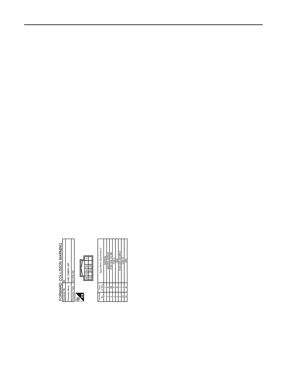
ICC SENSOR INTEGRATED UNIT
Fail-Safe
INFOID:0000000005502038
If a malfunction occurs in the system, a chime sounds a beep, and ICC sensor integrated unit cancels the con-
trol. Then the ICC system warning lamp in the combination meter illuminates.
DTC Inspection Priority Chart
INFOID:0000000005502039
If multiple DTCs are detected simultaneously, check them one by one depending on the following DTC inspec-
tion priority chart.
JCOWA0297GB

CCS
ICC SENSOR INTEGRATED UNIT
CCS-417
< ECU DIAGNOSIS INFORMATION >
[FCW]
C
D
E
F
G
H
I
J
K
L
M
B
N
P
A
DTC Index
INFOID:0000000005502040
NOTE:
• The details of time display are as per the following.
- CRNT: A malfunction is detected now
- PAST: A malfunction was detected in the past
• IGN counter is displayed on FFD (Freeze Frame Data).
- 0: The malfunctions that are detected now
CAN communication system (U1000, U1010)
- 1 - 39: It increases like 0
→
1
→
2 ··· 38
→
39 after returning to the normal condition whenever the ignition
switch OFF
→
ON. It returns to 0 when a malfunction is detected again in the process.
- If it is over 39, it is fixed to 39 until the self-diagnosis results are erased.
Other than CAN communication system (Other than U1000, U1010)
Priority
Detected items (DTC)
1
• U1000: CAN COMM CIRCUIT
• U1010: CONTROL UNIT (CAN)
2
• C1A31: BCU INTERNAL MALF
• C1F02: APA C/U MALF
3
• C1A01: POWER SUPPLY CIR
• C1A02: POWER SUPPLY CIR 2
• C1A04: ABS/TCS/VDC CIRC
• C1A05: BRAKE SW/STOP L SW
• C1A06: OPERATION SW CIRC
• C1A08: PRESS SEN CIRCUIT
• C1A09: BOOSTER SOL/V CIRC
• C1A10: RELEASE SW CIRC
• C1A11: PRESSURE CONTROL
• C1A12: LASER BEAM OFFCNTR
• C1A13: STOP LAMP RLY FIX
• C1A14: ECM CIRCUIT
• C1A16: RADAR STAIN
• C1A18: LASER AIMING INCMP
• C1A21: UNIT HIGH TEMP
• C1A22: BCU CIRCUIT
• C1A24: NP RANGE
• C1A28: BCU PWR SUPLY CIR
• C1A29: BCU PWR SUPLY CIR2
• C1A30: BCU CAN COMM CIRC
• C1A32: IBA FLAG STUCK
• C1A33: CAN TRANSMISSION ERROR
• C1A34: COMMAND ERROR
• C1A35: APA CIR
• C1A36: APA CAN COMM CIR
• C1A37: APA CAN CIR2
• C1A38: APA CAN CIR1
• C1A39: STRG SEN CIR
• C1A40: SYSTEM SW CIRC
• C1F01: APA MOTOR MALF
• C1F05: APA PWR SUPLY CIR
• U0121: VDC CAN CIR2
• U0126: STRG SEN CAN CIR1
• U0129: BCU CAN CIR2
• U0401: ECM CAN CIR1
• U0402: TCM CAN CIR1
• U0415: VDC CAN CIR1
• U0418: BCU CAN CIR1
• U0428: STRG SEN CAN CIR2
4
• C1A03: VHCL SPEED SE CIRC
5
• C1A15: GEAR POSITION
6
• C1A00: CONTROL UNIT
CCS-418
< ECU DIAGNOSIS INFORMATION >
[FCW]
ICC SENSOR INTEGRATED UNIT
- 1 - 49: It increases like 0
→
1
→
2 ··· 38
→
49 after returning to the normal condition whenever the ignition
switch OFF
→
ON. It returns to 0 when a malfunction is detected again in the process.
- If it is over 49, it is fixed to 49 until the self-diagnosis results are erased.
NOTE:
IBA system automatically returns to ON, when erasing self diagnosis result.
×
: Applicable
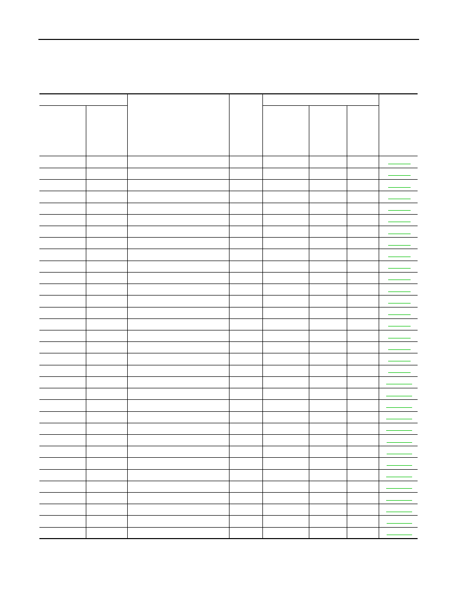
DTC
CONSULT-III display
ICC sys-
tem
warning
lamp
Fail-safe function
Reference
CONSULT-III
On board
display
Vehicle-to-ve-
hicle distance
control mode
Conven-
tional
(fixed
speed)
cruise con-
trol mode
IBA sys-
tem
C1A00
0
CONTROL UNIT
×
×
×
×
C1A01
1
POWER SUPPLY CIR
×
×
×
×
C1A02
2
POWER SUPPLY CIR 2
×
×
×
×
C1A03
3
VHCL SPEED SE CIRC
×
×
×
×
C1A04
4
ABS/TCS/VDC CIRC
×
×
×
×
C1A05
5
BRAKE SW/STOP L SW
×
×
×
×
C1A06
6
OPERATION SW CIRC
×
×
×
C1A08
8
PRESS SEN CIRCUIT
×
×
×
×
C1A09
9
BOOSTER SOL/V CIRC
×
×
×
×
C1A10
10
RELEASE SW CIRC
×
×
×
×
C1A11
11
PRESSURE CONTROL
×
×
×
×
C1A12
12
LASER BEAM OFFCNTR
×
×
×
C1A13
13
STOP LAMP RLY FIX
×
×
×
C1A14
14
ECM CIRCUIT
×
×
×
C1A15
15
GEAR POSITION
×
×
×
×
C1A16
16
RADAR STAIN
×
×
×
C1A18
18
LASER AIMING INCMP
×
×
×
C1A21
21
UNIT HIGH TEMP
×
×
×
×
C1A22
22
BCU CIRCUIT
×
×
×
×
C1A24
24
NP RANGE
×
×
×
×
C1A28
28
BCU PWR SUPLY CIR
×
×
×
×
C1A29
29
BCU PWR SUPLY CIR2
×
×
×
×
C1A30
30
BCU CAN COMM CIRC
×
×
×
×
C1A31
31
BCU INTERNAL MALF
×
×
×
×
C1A32
32
IBA FLAG STUCK
×
×
×
×
C1A33
33
CAN TRANSMISSION ERROR
×
×
×
×
C1A34
34
COMMAND ERROR
×
×
×
×
C1A35
35
APA CIR
×
×
C1A36
36
APA CAN COMM CIR
×
×
C1A37
133
APA CAN CIR2
×
×
×
C1A38
132
APA CAN CIR1
×
×
×
C1A39
39
STRG SEN CIR
×
×
×
C1A40
40
SYSTEM SW CIRC
×
×
×
×

CCS
ICC SENSOR INTEGRATED UNIT
CCS-419
< ECU DIAGNOSIS INFORMATION >
[FCW]
C
D
E
F
G
H
I
J
K
L
M
B
N
P
A
NO DTC IS
DETECTED.
FURTHER
TESTING
MAY BE RE-
QUIRED
55
NO DTC IS DETECTED.
FURTHER TESTING
MAY BE REQUIRED.
—
—
—
—
—
C1F01
91
APA MOTOR MALF
×
×
C1F02
92
APA C/U MALF
×
×
C1F05
95
APA PWR SUPLY CIR
×
×
U0121
127
VDC CAN CIR2
×
×
×
×
U0126
130
STRG SEN CAN CIR1
×
×
×
U0129
125
BCU CAN CIR2
×
×
×
×
U0401
120
ECM CAN CIR1
×
×
×
×
U0402
122
TCM CAN CIR1
×
×
×
×
U0415
126
VDC CAN CIR1
×
×
×
×
U0418
124
BCU CAN CIR1
×
×
×
×
U0428
131
STRG SEN CAN CIR2
×
×
×
U1000
100
CAN COMM CIRCUIT
×
×
×
×
U1010
110
CONTROL UNIT (CAN)
×
×
×
×
DTC
CONSULT-III display
ICC sys-
tem
warning
lamp
Fail-safe function
Reference
CONSULT-III
On board
display
Vehicle-to-ve-
hicle distance
control mode
Conven-
tional
(fixed
speed)
cruise con-
trol mode
IBA sys-
tem
Нет комментариевНе стесняйтесь поделиться с нами вашим ценным мнением.
Текст