Infiniti FX35, FX50 (S51). Manual — part 381
CCS-344
< ECU DIAGNOSIS INFORMATION >
[DCA]
BRAKE BOOSTER CONTROL UNIT
BRAKE BOOSTER CONTROL UNIT
Reference Value
INFOID:0000000005501997
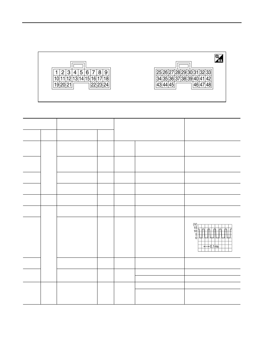
TERMINAL LAYOUT
PHYSICAL VALUES
JPOIA0106ZZ
Terminal No.
(Wire color)
Description
Condition
Value
(Approx.)
+
−
Signal name
Input/
Output
1
(W)
Ground
Battery power supply
—
Ignition
switch
OFF
—
Battery voltage
2
(W)
Battery power supply
—
Ignition
switch
OFF
—
Battery voltage
5
(P)
ITS communication-L
Input/
Output
—
—
—
6
(SB)
Release switch power
supply
—
Ignition
switch ON
—
10 V
8
(R)
24
(O)
Brake pressure sensor
power supply
—
Ignition
switch ON
—
5 V
10
(G)
Ground
Booster solenoid pow-
er supply
—
Ignition
switch ON
—
12 V
12
(R)
Booster solenoid
ground
Output
Ignition
switch ON
At “BOOSTER SOL/V ” test
of “Active test”
14
(L)
ITS communication-H
Input/
Output
—
—
—
15
(V)
Release switch (nor-
mal close)
—
Ignition
switch ON
Press the brake pedal
0 V
Brake pedal not depressed
10 V
17
(G)
24
(O)
Brake pressure sensor
signal
Input
Ignition
switch ON
Brake pedal not depressed
0.5 V
Press the brake pedal
0.5 - 3.5 V
Note: The harder the brake is
pressed, the higher the voltage.
PKIB1763J

CCS
BRAKE BOOSTER CONTROL UNIT
CCS-345
< ECU DIAGNOSIS INFORMATION >
[DCA]
C
D
E
F
G
H
I
J
K
L
M
B
N
P
A
19
(B)
Ground
Ground
—
Ignition
switch ON
—
0 V
20
(B)
Ground
—
Ignition
switch ON
—
0 V
21
(GR)
ICC warning chime
signal
Output
Ignition
switch ON
ICC warning chime not oper-
ating
12 V
ICC warning chime opera-
tion
0 V
22
(BR)
Release switch
(normal open)
Input
Ignition
switch ON
Brake pedal depressed
10 V
Brake pedal not depressed
0 V
24
(O)
Brake pressure sensor
ground
—
—
—
—
33
(G)
Ignition power supply
—
Ignition
switch ON
—
Battery voltage
40
(SB)
IBA OFF switch
Input
Ignition
switch ON
IBA OFF switch pressed
0 V
IBA OFF switch not pressed
12 V
42
(G)
Ignition power supply
—
Ignition
switch ON
—
Battery voltage
46
(B)
Ground
—
Ignition
switch ON
—
0 V
47
(LG)
ICC brake hold relay
drive signal
Output
Ignition
switch ON
—
0 V
At “STOP LAMP” test of “Ac-
tive test”
12 V
Terminal No.
(Wire color)
Description
Condition
Value
(Approx.)
+
−
Signal name
Input/
Output
CCS-346
< ECU DIAGNOSIS INFORMATION >
[DCA]
ACCELERATOR PEDAL ACTUATOR
ACCELERATOR PEDAL ACTUATOR
Reference Value
INFOID:0000000005501998
VALUES ON THE DIAGNOSIS TOOL
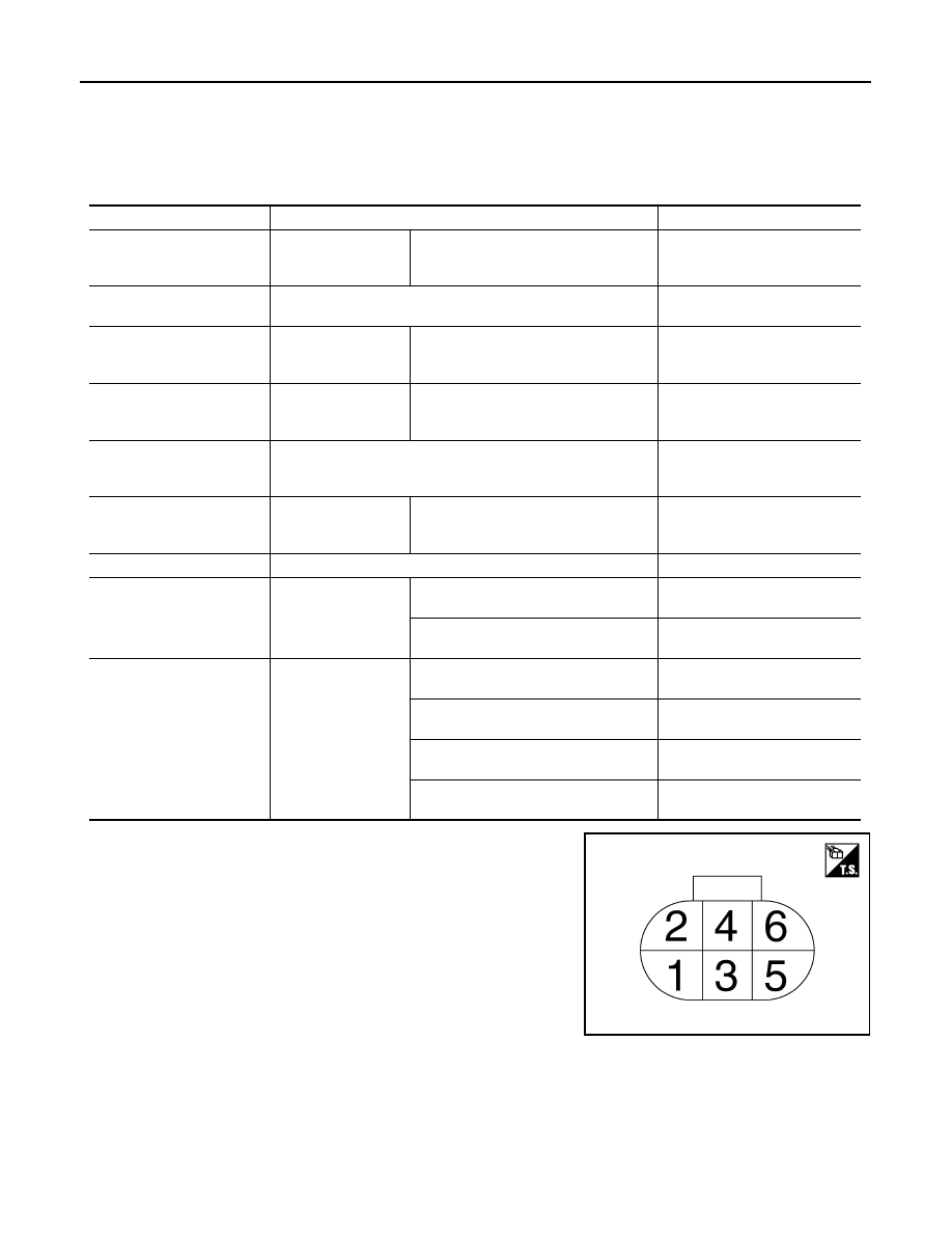
TERMINAL LAYOUT
PHYSICAL VALUES
Monitor item
Condition
Value/Status
TGT FBK FRC
Drive the vehicle and
operate the DCA sys-
tem
When the ICC sensor integrated unit is
controlling the accelerator pedal actua-
tor
It changes with the demand from
the ICC sensor integrated unit.
TGT MOT POSI
NOTE:
The item is indicated, but not used.
—
ACT MOT POSI
Engine running
Depress accelerator pedal
It changes according to the de-
pressed amount of accelerator
pedal
AP OPEN
Engine running
Depress accelerator pedal
It changes according to the de-
pressed amount of accelerator
pedal
APA TEMP
Engine running
Display the accelerator pedal ac-
tuator integrated motor tempera-
ture
APA CURRENT
Drive the vehicle and
operate the DCA sys-
tem
When the ICC sensor integrated unit is
controlling the accelerator pedal actua-
tor
Display the accelerator pedal ac-
tuator motor operation consump-
tion current
APA PWR
Ignition switch ON
Battery voltage
APA OPE STATS
Engine running
When the accelerator pedal actuator
control is permitted
On
When the accelerator pedal actuator
control is invalid
Off
APA STATS
Engine running
When the accelerator pedal actuator is
normal
Ready
When the accelerator pedal actuator is
temporarily malfunctioning
TP NG
When the accelerator pedal actuator is
malfunctioning
NG
During the accelerator pedal actuator
operation preparations
Init
JPOIA0104ZZ

CCS
ACCELERATOR PEDAL ACTUATOR
CCS-347
< ECU DIAGNOSIS INFORMATION >
[DCA]
C
D
E
F
G
H
I
J
K
L
M
B
N
P
A
Terminal No.
(Wire color)
Description
Condition
Value
(Approx.)
+
–
Signal name
Input/
Output
1
(R)
Ground
Ignition power supply
Input
Ignition switch ON
Battery voltage
2
(O)
Battery power supply
Input
Ignition switch OFF
Battery voltage
3
(P)
ITS communication-L
Input/
Output
—
—
4
(B)
Ground
—
Ignition switch ON
0 V
5
(L)
ITS communication-H
Input/
Output
—
—
Нет комментариевНе стесняйтесь поделиться с нами вашим ценным мнением.
Текст