Infiniti FX35, FX50 (S51). Manual — part 1540
POWER WINDOW MAIN SWITCH
PWC-221
< ECU DIAGNOSIS INFORMATION >
[FRONT WINDOW ANTI-PINCH]
C
D
E
F
G
H
I
J
L
M
A
B
PWC
N
O
P
If fail-safe control, the system changes to a non-initialized condition and the following function do not operate.
• Auto-up operation
• Anti-pinch function
• Retained power function
When fail-safe control is activated, perform initialization procedure to recover. If a malfunction is detected in
power window switch or more, fail-safe control is activated again.
Malfunction
Malfunction condition
Pulse sensor malfunction
When one pulse signal that is the specified value or more is detected continuously for the specified
time or more, while door glass is being operated UP or DOWN.
Both pulse sensors mal-
function
When both pulse signals are not detected continuously for the specified time or more, while door
glass is being operated UP or DOWN.
Pulse direction malfunc-
tion
When a pulse signal indicating that window is moving in the opposite direction against the power win-
dow motor is detected for the specified value or more, while door glass is being operated UP or
DOWN.
Glass recognition position
malfunction 1
When the actual door glass position that is out of specified value is detected compared to the door
glass fully closed position memorized in module, while door glass is being operated UP or DOWN.
Glass recognition position
malfunction 2
When pulse count that is out of the door glass full stroke value or more is detected, while door glass
is being operated UP or DOWN.
Fully closed position up-
date malfunction
When door glass is continuously operated UP or DOWN for the specified value or more without fully
closing door glass (approximately 10 time or more).
PWC-222
< ECU DIAGNOSIS INFORMATION >
[FRONT WINDOW ANTI-PINCH]
FRONT POWER WINDOW SWITCH
FRONT POWER WINDOW SWITCH
Reference Value
INFOID:0000000005248315
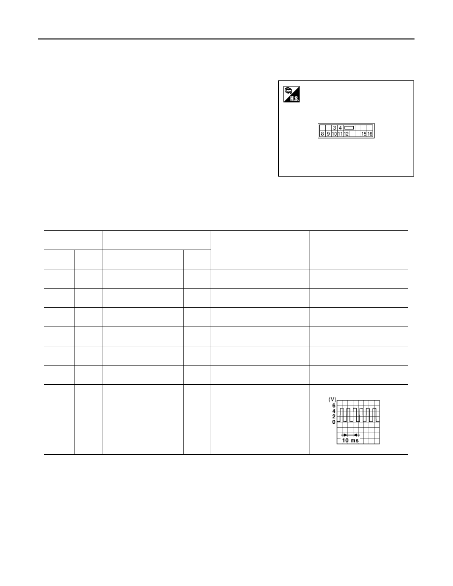
TERMINAL LAYOUT
PHYSICAL VALUES
FRONT POWER WINDOW SWITCH
JMKIA0134ZZ
Terminal No.
(wire color)
Description
Condition
Voltage [V]
(Approx.)
+
-
Signal name
Input/
Output
3
(LG)
Ground
Encoder ground
—
—
0
4
(W)
Ground
Encoder power supply
Output
When ignition switch ON or pow-
er window timer operates
Battery voltage
8
(L)
Ground
Power window motor
UP signal
Output
When power window motor is
UP at operated.
Battery voltage
9
(G)
Ground
Power window motor
DOWN signal
Output
When power window motor is
DOWN at operated.
Battery voltage
10
(Y)
Ground
Battery power supply
Input
—
Battery voltage
11
(B)
Ground
Ground
—
—
0
12
(P)
Ground
Encoder pulse signal 1
Input
When power window motor oper-
ates.
JMKIA0070GB
FRONT POWER WINDOW SWITCH
PWC-223
< ECU DIAGNOSIS INFORMATION >
[FRONT WINDOW ANTI-PINCH]
C
D
E
F
G
H
I
J
L
M
A
B
PWC
N
O
P
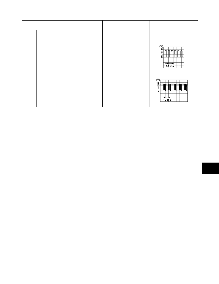
15
(R)
Ground
Encoder pulse signal 2
Input
When power window motor oper-
ates.
16
(V)
Ground
Power window serial link
Input/
Output
IGN SW ON or power window
timer operating.
Terminal No.
(wire color)
Description
Condition
Voltage [V]
(Approx.)
+
-
Signal name
Input/
Output
JMKIA0070GB
JPMIA0013GB
PWC-224
< ECU DIAGNOSIS INFORMATION >
[FRONT WINDOW ANTI-PINCH]
FRONT POWER WINDOW SWITCH
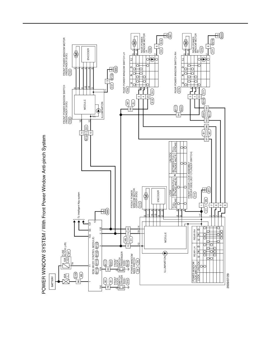
Wiring Diagram - POWER WINDOW CONTROL SYSTEM -
INFOID:0000000005621778
JCKWA3060GB
Нет комментариевНе стесняйтесь поделиться с нами вашим ценным мнением.
Текст