Infiniti FX35, FX50 (S51). Manual — part 320
CCS-100
< DTC/CIRCUIT DIAGNOSIS >
[ICC (FULL SPEED RANGE)]
C1A22 BCU CIRCUIT
2.
Check ICC brake switch for correct installation. Refer to
BR-7, "Inspection and Adjustment"
Is the inspection result normal?
YES
>> GO TO 4.
NO
>> Adjust ICC brake switch installation. Refer to
BR-7, "Inspection and Adjustment"
4.
ICC BRAKE SWITCH INSPECTION
1.
Disconnect ICC brake switch connector.
2.
Check ICC brake switch. Refer to
CCS-64, "Component Inspection (ICC Brake Switch)"
.
Is the inspection result normal?
YES
>> GO TO 7.
NO
>> Replace the ICC brake switch.
5.
CHECK STOP LAMP FOR ILLUMINATION
Check stop lamp illumination.
Is the inspection result normal?
YES
>> GO TO 6.
NO
>> Check the stop lamp circuit, and repair or replace the malfunctioning parts.
6.
CHECK ICC BRAKE HOLD RELAY
1.
Turn the ignition switch OFF.
2.
Remove ICC brake hold relay.
3.
Check for continuity between ICC brake hold relay terminals.
Is the inspection result normal?
YES
>> GO TO 7.
NO
>> Replace ICC brake hold relay.
7.
CHECK HARNESS BETWEEN ECM AND ICC BRAKE HOLD RELAY
1.
Disconnect ECM connector.
2.
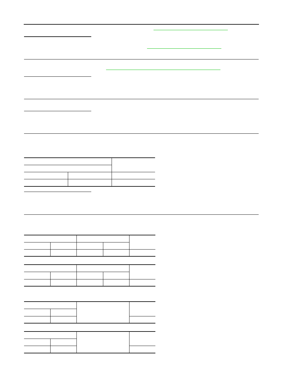
Check for continuity between the ECM harness connector and ICC brake hold relay harness connector.
VQ35HR
VK50VE
3.
Check for continuity between ECM harness connector and ground.
VQ35HR
VK50VE
ICC brake hold relay
Continuity
Terminal
3
4
Existed
7
6
Not existed
ECM
ICC brake hold relay
Continuity
Connector
Terminal
Connector
Terminal
M107
122
E91
6
Existed
ECM
ICC brake hold relay
Continuity
Connector
Terminal
Connector
Terminal
M160
110
E91
6
Existed
ECM
Ground
Continuity
Connector
Terminal
M107
122
Not existed
ECM
Ground
Continuity
Connector
Terminal
M160
110
Not existed
CCS
C1A22 BCU CIRCUIT
CCS-101
< DTC/CIRCUIT DIAGNOSIS >
[ICC (FULL SPEED RANGE)]
C
D
E
F
G
H
I
J
K
L
M
B
N
P
A
Is the inspection result normal?
YES
>> GO TO 8.
NO
>> Repair the harnesses or connectors.
8.
CHECK HARNESS BETWEEN ECM AND ICC BRAKE SWITCH
1.
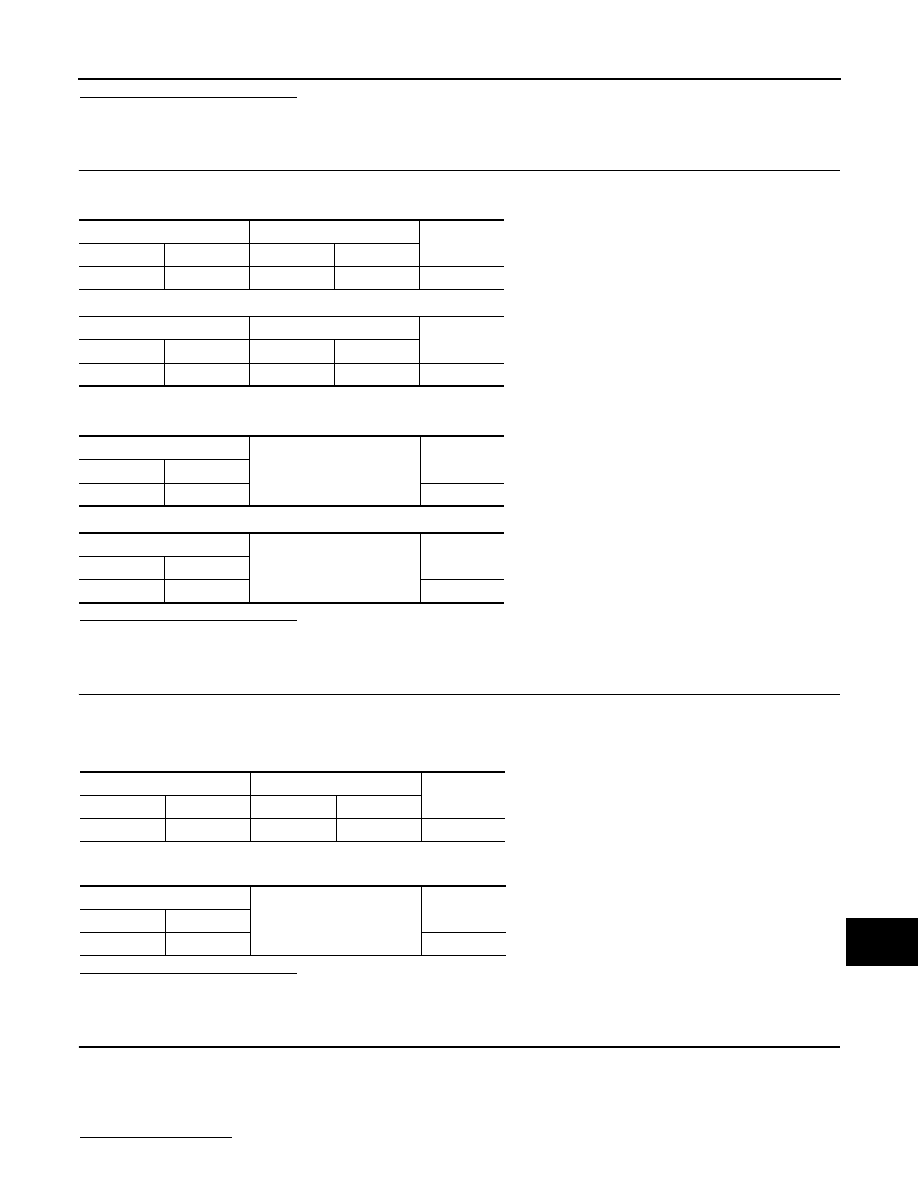
Check for continuity between the ECM harness connector and ICC brake switch harness connector.
VQ35HR
VK50VE
2.
Check for continuity between ECM harness connector and ground.
VQ35HR
VK50VE
Is the inspection result normal?
YES
>> GO TO 9.
NO
>> Repair the harnesses or connectors.
9.
CHECK HARNESS BETWEEN ICC BRAKE SWITCH AND ICC BRAKE HOLD RELAY
1.
Disconnect ICC brake switch connector.
2.
Check for continuity between ICC brake switch harness connector and ICC brake hold relay harness con-
nector.
3.
Check for continuity between ICC brake switch harness connector and ground.
Is the inspection result normal?
YES
>> GO TO 10.
NO
>> Repair the harnesses or connectors.
10.
PERFORM SELF-DIAGNOSIS OF ECM
1.
Connect all connectors again if the connectors are disconnected.
2.
Turn the ignition switch ON.
3.
Perform “All DTC Reading”.
4.
Check if any DTC is detected in “Self Diagnostic Result” of “ENGINE”.
Is any DTC detected?
ECM
ICC brake switch
Continuity
Connector
Terminal
Connector
Terminal
M107
126
E114
2
Existed
ECM
ICC brake switch
Continuity
Connector
Terminal
Connector
Terminal
M160
117
E114
2
Existed
ECM
Ground
Continuity
Connector
Terminal
M107
126
Not existed
ECM
Ground
Continuity
Connector
Terminal
M160
117
Not existed
ICC brake switch
ICC brake hold relay
Continuity
Connector
Terminal
Connector
Terminal
E114
1
E91
4
Existed
ICC brake switch
Ground
Continuity
Connector
Terminal
E114
1
Not existed

CCS-102
< DTC/CIRCUIT DIAGNOSIS >
[ICC (FULL SPEED RANGE)]
C1A22 BCU CIRCUIT
YES
>> Perform diagnosis on the detected DTC and repair or replace the malfunctioning parts. Refer to
(VK50VE).
NO
>> Replace the brake booster control unit.
Special Repair Requirement
INFOID:0000000005501651
DESCRIPTION
Perform the action test after adjusting the laser beam aiming of ICC sensor integrated unit when the following
operation is performed.
• Removal and installation of ICC sensor integrated unit
• Replacement of ICC sensor integrated unit
SPECIAL REPAIR REQUIREMENT
1.
LASER BEAM AIMING ADJUSTMENT OF ICC SENSOR INTEGRATED UNIT
Adjust the laser beam aiming of the ICC sensor integrated unit. Refer to
>> GO TO 2.
2.
CHECK ICC SYSTEM
1.
Erase the “Self Diagnostic Result”, and then perform “All DTC Reading” again after performing the action
test. (Refer to
CCS-18, "ACTION TEST : Description"
2.
Check that the ICC system is normal.
>> WORK END

CCS
C1A24 NP RANGE
CCS-103
< DTC/CIRCUIT DIAGNOSIS >
[ICC (FULL SPEED RANGE)]
C
D
E
F
G
H
I
J
K
L
M
B
N
P
A
C1A24 NP RANGE
Description
INFOID:0000000005501652
ICC sensor integrated unit judges the NP position status from the shift position signal and current gear position
signal received from TCM via CAN communication.
DTC Logic
INFOID:0000000005501653
DTC DETECTION LOGIC
NOTE:
If DTC “C1A24” is detected along with DTC “U1000”, first diagnose the DTC “U1000”. Refer to
.
DTC CONFIRMATION PROCEDURE
1.
CHECK DTC REPRODUCE (1)
1.
Start the engine.
2.
Turn the MAIN switch of ICC system ON.
3.
Wait for approximately 5 minutes or more after shifting the selector lever to “P” position.
4.
Perform “All DTC Reading” with CONSULT-III.
5.
Check if the “C1A24” is detected as the current malfunction in “Self Diagnostic Result” of “ICC”.
Is “C1A24” detected as the current malfunction?
YES
>> Refer to
CCS-103, "Diagnosis Procedure"
NO
>> GO TO 2.
2.
CHECK DTC REPRODUCE (2)
1.
Wait for approximately 5 minutes or more after shifting the selector lever to “N” position.
2.
Perform “All DTC Reading”.
3.
Check if the “C1A24” is detected as the current malfunction in “Self Diagnostic Result” of “ICC”.
Is “C1A24” detected as the current malfunction?
YES
>> Refer to
CCS-103, "Diagnosis Procedure"
NO
>> Refer to
GI-36, "Intermittent Incident"
.
Diagnosis Procedure
INFOID:0000000005501654
1.
CHECK SELF-DIAGNOSIS RESULTS
Check if “U1000” is detected other than “C1A24” in “Self Diagnostic Result” of “ICC”.
Is “U1000” detected?
YES
>> Perform the CAN communication system inspection. Repair or replace the malfunctioning parts.
.
NO
>> GO TO 2.
2.
CHECK NP POSITION SWITCH SIGNAL
Check that “NP RANGE SW” operates normally in “DATA MONITOR” of “ICC”.
Is the inspection result normal?
YES
>> GO TO 3.
NO
>> Replace the ICC sensor integrated unit. Refer to
3.
CHECK TCM DATA MONITOR
Check that “SLCT LVR POSI” operates normally in “DATA MONITOR” of “TRANSMISSION”.
DTC
(On board dis-
play)
Trouble diagnosis name
DTC detecting condition
Possible causes
C1A24
(24)
NP RANGE
If the shift position signal and the current gear
position signal, transmitted from TCM via CAN
communication, are inconsistent
• TCM
• Transmission range switch
Нет комментариевНе стесняйтесь поделиться с нами вашим ценным мнением.
Текст